Wiring – Edwards Signaling 260-CO User Manual
Page 5
P/N 3102002-EN • REV 01 • ISS 27AUG12
5 / 8
Wiring
All wiring must conform to the NFPA 70 National Electric Code,
UL 2075 Standard for Gas and Vapor Detectors and Sensors,
NFPA 720 Standard for the Installation of Carbon Monoxide
(CO) Detection and Warning Equipment, applicable codes, and
the local AHJ.
Wire the 260-CO detector as appropriate for your facility. There
are three typical wiring configurations:
•
Single device and single zone (Figure 4)
•
Multiple devices in a single zone (Figure 5)
•
Multiple devices with separate alarm and trouble zones
(Figure 6)
Figure 4: Single device, single zone configuration
C
NC
NC
NO
C
(1)
(2)
(3)
+ –
(1) End-of-line device (provided by the life safety system)
(2) Alarm initiating device circuit (IDC)
(3) Power (see “Specifications” on page 7)
Note: Relay is shown in the normal state for this detector.
Tandem Interconnect:
When wiring your facility with multiple 260-CO detectors for
tandem interconnect, you must use a Single Circuit Reversal
Module (see Table 2). On alarm, the module disconnects the
detector from its normal power supply and applies reverse
polarity from the notification appliance circuit. Applying reverse
polarity causes the sounders to activate on other 260-CO
detectors that are on the same loop. Only the initiating detector
will sound and blink red. All others in tandem mode will sound
but not blink red.
Table 2: Models [1]
Number Description
ESL 405-01
24 VDC Single Circuit Polarity Reversal Module
ESL 405-03
12 VDC Single Circuit Polarity Reversal Module
ESL 405-05
12/24 VDC Single Circuit Polarity Reversal Module [2]
[1] A 204 series power supervision relay is not required.
[2] When using the ESL 405-05 model, refer to the wiring instructions
that came with the device.
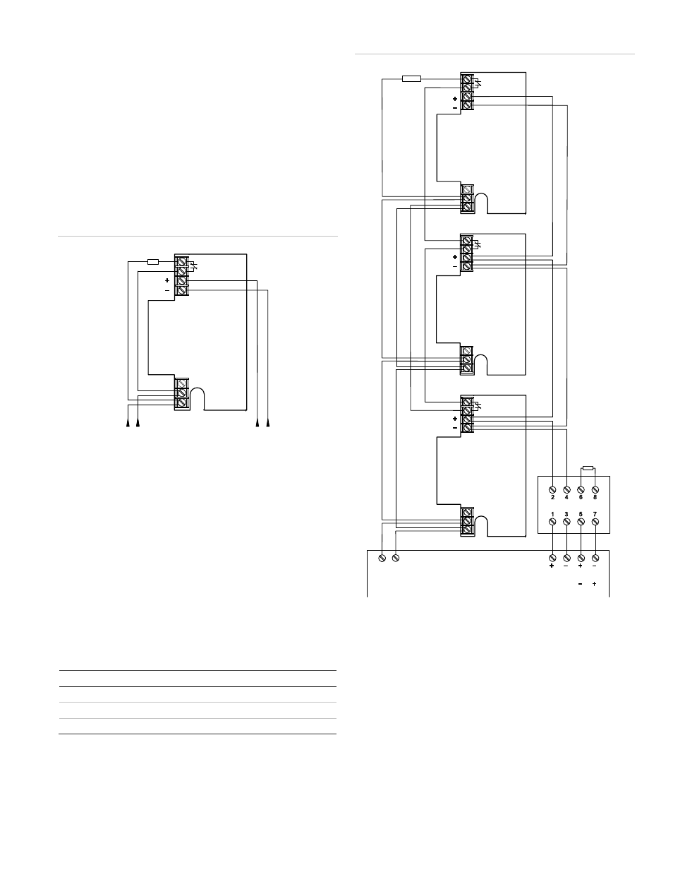
Figure 5: Multiple devices, single zone configuration
(1)
(1)
(2)
(3)
(4)
(5)
(7)
(6)
C
NC
NC
NO
C
C
NC
NC
NO
C
C
NC
NC
NO
C
(1) End-of-line device (supplied by life safety system)
(2) ESL 405-03 (12 VDC) or ESL 405-01 (24 VDC) polarity reversal
module
(3) Control
panel
(4) Alarm
IDC
(5) Power 12/24 VDC
(6) Notification appliance circuit (NAC) from 12 VDC control panel
(7) Notification appliance circuit (NAC) from 24 VDC control panel
Note: Relay is shown in the normal state for this detector.