Edwards Signaling 260-CO User Manual
Page 4
4 / 8
P/N 3102002-EN • REV 01 • ISS 27AUG12
To install the 260-CO detector:
1. Run the 260-CO detector wiring to the detector location.
2. Carefully remove the cover from the detector using a
small, flat screwdriver blade in the slot on the left side of
the detector cover.
3. The mounting hole pattern is for a single-gang electrical
box or mounting ring. Use the base as a template to mark
the two screw hole locations on the mounting surface or
mount on a single-gang box (not provided). The unit can
be mounted vertically or horizontally.
4. Install two screws on the marks. If necessary, use wall
anchors.
5. Line up the base with the screws, pull the wires through
the square holes, and then slide the base over the screws.
See Figure 2.
6. Strip 3/8 in. of insulation from each wire.
7. Determine the correct wiring, and then insert the wires
under the appropriate screw terminals. See “Wiring” on
page 5.
8. Tighten both screws to secure the base to the wall.
9. Replace the detector cover.
10. Apply power. The LED should flash green for about four
seconds, and then pulse green.
11. Test in accordance with “Testing” on page 6.
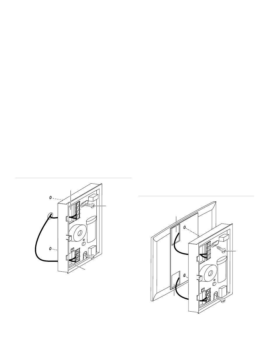
Figure 2: Installing the 260-CO detector
(1)
(3)
(2)
(1) Trouble relay and power wiring hole
(2) Alarm relay wiring hole
(3) Mounting screws (2X)
The 250-COPLT adapter plate
The 260-CO detector has an optional adapter mounting plate.
Use the 250-COPLT adapter plate when replacing a 240-COe
with a 260-CO to cover the footprint of the 240-COe. To
purchase the plate, order P/N 250-COPLT-5PKG.
To install the detector with the 250-COPLT adapter plate:
1. Run the 260-CO detector wiring to the detector location.
2. Using the 250-COPLT wall plate for a template, trace the
perimeter of the two square holes on the mounting
surface. Also mark the two screw locations.
3. Cut out the two square holes.
4. Install two screws on the marks. If necessary, use wall
anchors. See Figure 3.
5. Mount the wall plate but do not fully tighten the screws.
6. Carefully remove the cover from the detector using a
small, flat screwdriver blade in the slot on the left side of
the detector cover.
7. Pull the wires through the square holes on both the wall
plate and the 260-CO base, and then slide the detector
base over the screws.
8. Strip 3/8 in. of insulation from each wire.
9. Determine the correct wiring, and then insert the wires
under the appropriate screw terminals. See “Wiring.”
10. Tighten both screws to secure the base to the wall plate.
11. Replace the detector cover.
12. Apply power. The LED should flash green for
approximately four seconds, and then pulse green.
13. If required by the AHJ or local codes, affix the supplied CO
Warning Label (P/N 10634757) in proximity to the
detector.
14. Test in accordance with “Testing” on page 6.
Figure 3: Installing the 260-CO detector with the adapter plate
(1)
(2)
(3)
(1) Trouble relay and power wiring hole
(2) Alarm relay wiring hole
(3) Mounting screws for detector and mounting plate (2X)