Selecting the flash or rotation pattern, Maintenance – Edwards Signaling 94PLEDM Series User Manual
Page 2
2 / 4
P/N 3101962-EN • REV 02 • ISS 24JUN14
To wire the beacon for 24 VAC/VDC:
1. Connect the field wiring to the beacon wiring using wire
nuts (not supplied).
2. Connections depend on the voltage supply. Choose the
connections that match your power supply:
24 VAC: Connect the black lead to hot, and the red lead to
neutral.
24 VDC: Connect the red lead to positive (+), and the
black lead to negative (−). Connect the green lead to the
grounding point located in the beacon base.
Selecting the flash or rotation pattern
The beacon can be configured with one of 16 user-selectable
flash or rotation patterns using a push button (membrane
switch). The push button is located in the center of the
Edwards “shield logo” on the base of the beacon (Figure 1).
Table 1: Flash and rotation patterns
Pattern Description
1. Steady
On steady
2. S65
65 flashes per minute (FPM)
3. Light Burst
1,000 FPM (seven pulses),
440 ms off,
Repeat
4. Singular Burst
120 FPM
5. Binary Burst
65 double FPM
6. Quad Burst
65 quad FPM
7. iBurst
750 FPM (nine pulses),
480 FPM (one pulse),
85 FPM (six pulses),
460 FPM (one pulse)
8. Rotating 70 RPM
70 Rotations per minute
9. Rotating 84 RPM
84 Rotations per minute
10. Rotating 115 RPM
115 Rotations per minute
11. Rotating 180 RPM
180 Rotations per minute
12. Slow Rotating with Burst
4 rotations (84 RPM),
2 flash pulses (750 FPM),
Repeat
13. Flash Rotating with Burst
3 rotations (174 RPM),
4 flash pulses (750 FPM),
Repeat
14. Quad Flash with Pop
4 pulses (650 FPM), 204 ms off,
1 pulse (650 FPM), 356 ms off,
Repeat
15. Variable Rotating
164 RPM repeated in 6.6 s. on/off
cycles
16. Variable Flashing
248 FPM repeated in 4.1 s. on/off
cycles
To select a flash or rotation pattern:
1. Press and hold the push button for one second to switch
the beacon to the next pattern (Table 1).
2. Press and hold the push button for three seconds to set
the beacon to the first pattern (Steady).
Maintenance
Lens and dome replacement
WARNING:
Electrocution hazard. To prevent electrical shock,
disconnect the beacon from the supply circuit and allow five
minutes for stored energy to dissipate before disassembling.
To replace the lens or dome:
1. Release the latch on the clamp ring and remove the ring
holding the protective dome to the signal base. Lift the
dome straight up off of the signal base.
2. Loosen the three screws in the keyhole slots in the base of
the lens. Turn the lens clockwise and lift it straight up off of
the support plate.
3. Replace the lens by turning it counter-clockwise in the
keyhole slots, and then tightening the three screws.
4. Replace the dome and reinstall the clamp ring.
Cleaning
Caution
: To prevent damage to the lens or dome, do not use
abrasive materials or cleaners.
Periodically clean the lens surface with a soft cloth or sponge
and water or a mild detergent solution to maintain optimum
light visibility. Make sure the lens is completely dry before
assembling the beacon.
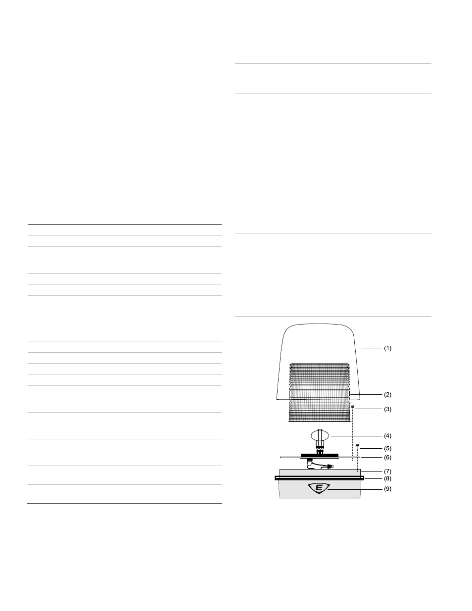
Figure 1: Installation
(1) Dome
(2) Lens
(3) Screw
(3X)
(4) LED
tower
(5) Screw (3X)
(6) LED light source support plate
(7) Beacon
base
(8) Clamp
ring
(9) Push
button