Edwards Signaling 94PLEDM Series User Manual
Edwards Signaling Safety
© 2014 UTC Fire & Security Americas Corporation, Inc.
1 / 4
P/N 3101962-EN • REV 02 • ISS 24JUN14
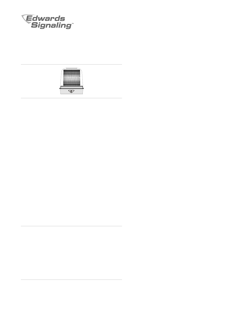
94PLEDM Series Rotating Polaris LED Beacon
Installation Sheet
Description
The 94PLEDM Series Rotating Polaris LED Beacon is UL and
cUL listed for general signaling use. The beacon is available in
120 VAC or multivoltage 12 VDC, 24 VAC, or 24 VDC models.
There are six lens colors to choose from, and a choice of black
or gray bases. The beacon utilizes high-power LED lights and
is suitable for indoor or outdoor use. The beacon is provided
with an enclosure rated for NEMA Type 4X and IP66.
The beacon is well suited for high ambient noise level areas,
especially where ear protection must be worn. The beacon is
also ideal for high vibration applications and areas where long
lamp life is advantageous. The beacon features a 360-degree
beam of light with 16 user-selectable flash or rotation patterns
including Steady. The patterns are selected by pressing the
Edwards logo push button. The factory setting is Light Burst.
The beacon is designed to be mounted on 3/4 in. NPT conduit
(indoor or outdoor). To maintain the NEMA Type 4X and IP66
ratings for outdoor installation, the beacon must be mounted
with the dome facing directly up. When installing the beacon
indoors in dry environments, it can be mounted in any position.
Installation
Install the beacon in accordance with the applicable
requirements in the latest edition of the National Electrical
Code, Canadian Electrical Code, and local codes.
WARNINGS
Electrocution hazard. To prevent electrical shock, ensure
that power is disconnected before installing the beacon
Electrocution hazard. To prevent leakage and potential
electrical shock, use care when disassembling the beacon
to prevent tearing of the permanently affixed gaskets
provided for the environmental integrity and ratings.
Electrocution hazard. To prevent leakage and potential
electrical shock when mounting outdoors, install the
beacon with the lens or dome facing directly up.
Note:
The beacon is designed to be conduit mounted.
To install the beacon:
1. Release the latch on the clamp ring and remove the ring
holding the protective dome to the signal base. Lift the
dome straight up off of the beacon base (Figure 1).
2. Loosen the three screws in the keyhole slots in the base of
the lens, turn the lens clockwise, and lift it off of the LED
light source support plate.
3. Remove the three screws holding the LED light source
support plate to the beacon base.
4. Gently grasp the LED tower and carefully lift the support
plate off of the beacon base.
Note:
The beacon mounts on a 3/4 in. NPT conduit pipe.
The female threaded entry is located on the bottom of the
base.
5. Route the field wiring from the appropriate power source
through the conduit, and then through the conduit
entrance hole in the beacon base.
6. Install the base on the conduit. Wrench-tighten for a leak
free seal.
7. Wire in accordance with “Wiring” below.
8. Place the connected wires inside the base and
reassemble the beacon (Figure 1).
9. Apply power and verify that the beacon operates properly.
Wiring
Wire this unit in accordance with all applicable local codes and
standards and the local authority having jurisdiction.
To wire the beacon for 120 VAC:
1. Using wire nuts (not supplied), connect the field wiring to
the beacon wiring.
2. Connect the beacon’s black lead to hot, and the white lead
to neutral. Connect the beacon’s green lead to the
grounding point located in the signal base.
To wire the beacon for 12 VDC:
1. Using wire nuts (not supplied), connect the field wiring to
the beacon wiring.
2. Connect the beacon’s red lead to positive (+), and the
black lead to negative (−).