Installation guidelines, Verify the duct air velocity, Select the appropriate sampling tube – Edwards Signaling E-PDD User Manual
Page 2
2 / 6
P/N 3101210 • REV 02 • ISS 28JAN13
Installation guidelines
To ensure correct operation, install the duct detector using the
following guidelines:
•
Install the duct smoke detector on a flat section of HVAC
duct between six and ten duct widths from any bends or
obstructions.
•
Install supply-side detectors at a point downstream from
the supply fan and after the air filter.
•
Install return-side detectors at a point before the return air
stream is diluted by outside air.
Verify the duct air velocity
In order to verify airflow direction and velocity, air must be
moving through the HVAC system.
To verify the duct air velocity:
1. Drill a small hole at the point where the duct smoke
detector is being installed.
2. Using the SD-VTK Air Velocity Test Kit and a suitable air
velocity meter, verify that the air velocity in the HVAC duct
falls within the specified operating range of the detector
and note which direction the air flows.
3. If the air velocity does not fall within the specified range,
relocate the detector and seal the hole in the HVAC duct.
Refer to Technical Bulletin P/N 3101212 for additional
information pertaining to installation locations.
Select the appropriate sampling tube:
•
Select a sampling tube that extends at least two-thirds
across the width of the duct.
•
For duct widths greater than 36 inches, use a sampling
tube that is longer than the width of the duct.
•
Sampling tubes are available in the following lengths:
Model
Description
SD-T8
8-inch sampling tube
SD-T18
18-inch sampling tube
SD-T24
24-inch sampling tube
SD-T36
36-inch sampling tube
SD-T42
48-inch sampling tube
SD-T60
60-inch sampling tube
SD-T78
78-inch sampling tube
SD-T120
120-inch sampling tube
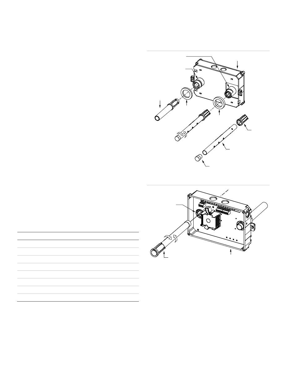
To assemble the detector:
1. Assemble the duct smoke detector as shown in Figure 2.
2. Rotate the air sampling tube so the inlet holes face the
direction of airflow.
3. The sampling tube is normally installed from the rear, but it
can also be installed from the front of the detector as
shown in Figure 3. This method requires that you remove
the detector cover.
Figure 2: Duct detector assembly
Detector
Sampling tube
socket
Exhaust tube
Thick
gasket
Thin
gasket
Exhaust tube
socket
Coupling
Sampling tube
(ordered separately)
Plug
Figure 3: Sampling tube installation
Sampling tube
connector
Sampling tube
(fully assembled)
Detector
To install the detector:
1. Attach the drill template to the HVAC duct at desired
mounting location.
2. Drill (or punch) the mounting holes where indicated.
Note:
Sampling tubes longer than 36 inches must be
supported at both ends of the duct.
3. If using an air sampling tube that is longer than the width
of the duct, drill a 3/4-inch hole on the opposite side of the
duct for tube to pass through.
4. Remove any rough edges from the holes.