Edwards Signaling E-NAC User Manual
Page 3
P/N 3101195 • REV 02 • REB 28JAN13
3 / 4
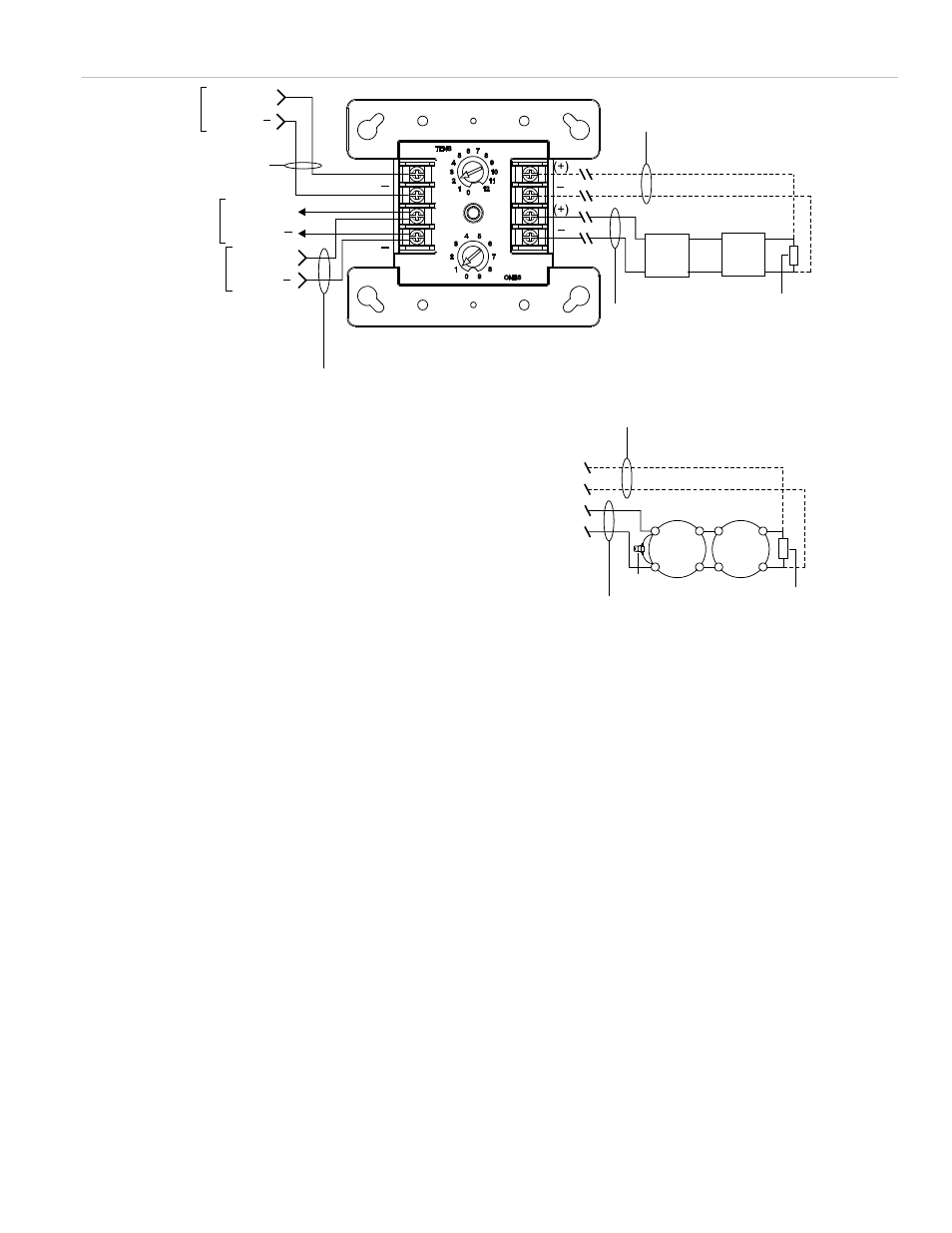
Figure 3: Module wiring
From
listed
power
supply
[2] [3] [5]
[4]
24 VDC (+)
24 VDC
Circuit wired
same as
diagram above
Style Z (Class A)
[1] [2] [5] [6]
Style Z (Class A)
[1] [2] [5] [6]
Style Y (Class B)
[1] [2] [5] [6]
Style Y (Class B)
[1] [2] [5] [6]
[8]
Typical bell circuit
Typical horn or
strobe circuit [7]
47 k EOLR
Used for
Class B only
Ω
47 k EOLR
Used for
Class B only
Ω
TB2
TB1
+
+
−
−
+
+
−
−
+
+
-
-
RETURN
NAC PWR. IN
NAC
SLC
(+)
(+)
From
previous
device
To next
device
SLC out (+)
SLC out
SLC in
SLC in (+)
( )
( )
( )
( )
( )
( )
( )
Notes
[1]
Maximum 25 Ω resistance per wire. Maximum circuit capacitance of 0.1 μF
[2] Maximum 12 AWG (2.5 mm
2
) wire; minimum 18 AWG (0.75 mm
2
) wire
[3] Refer to the control panel technical reference manual for wiring specifications
[4] If the NAC power riser is used for more than one notification zone, install in accordance with the survivability from attack by fire requirements
in NFPA 72
[5] Supervised
[6] Polarity shown in alarm condition. Polarity reverses on supervisory condition
[7] Typical synchronized temporal horn/strobe circuit when configured as Class A/B auto sync signal output module through programming
[8] Transient protection (see “Transient protection caution”)