Specifications, Wiring, Transient protection caution – Edwards Signaling E-NAC User Manual
Page 2
2 / 4
P/N 3101195 • REV 02 • REB 28JAN13
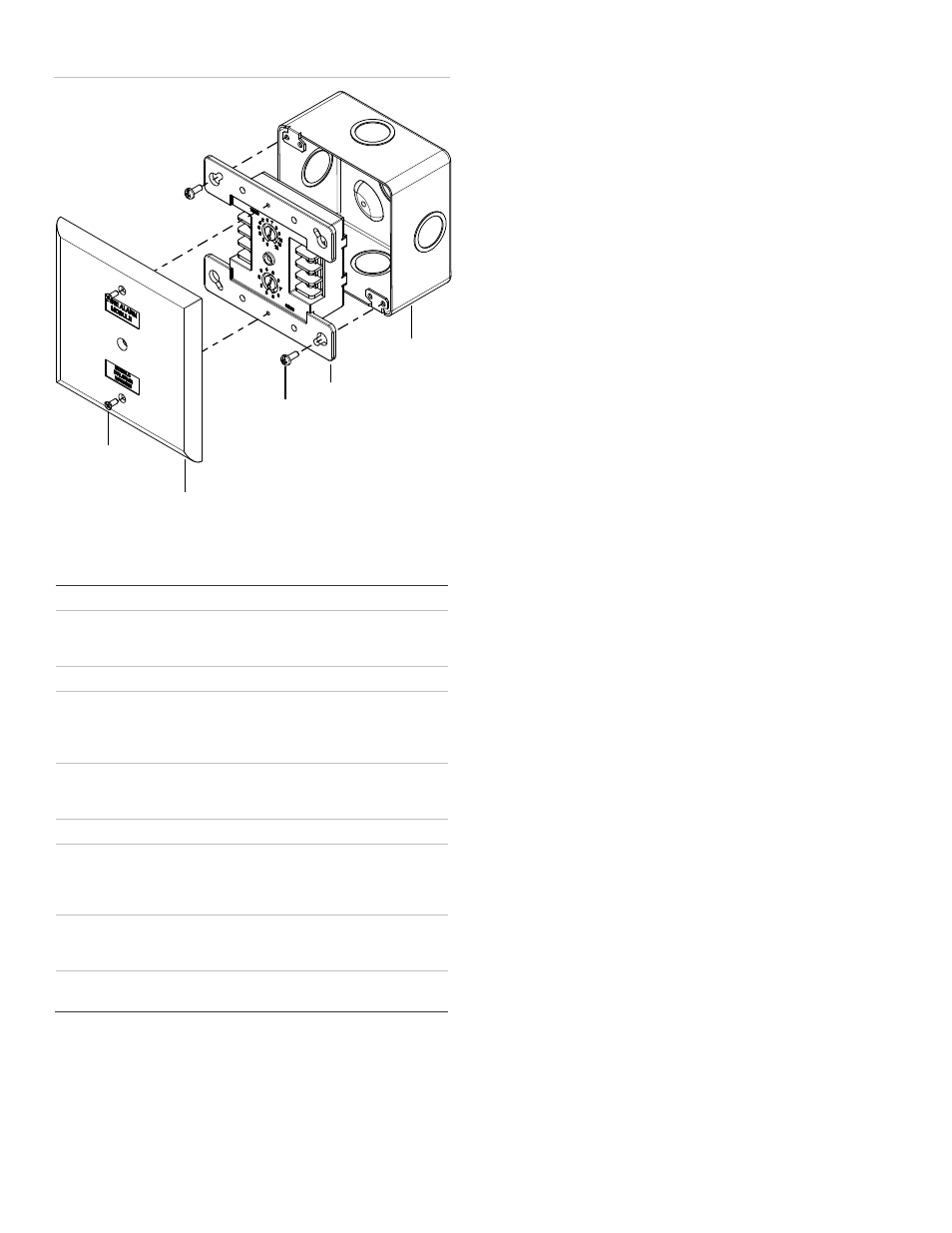
Figure 2: Module installation
Screw
4-24
screws
Module
Wall plate
Compatible
electrical box
Specifications
Communication line voltage
Maximum 20.6 V peak-to-peak
Current
Standby
Activated
350 μA
200 μA
Ground fault impedance
10 kΩ
Operating environment
Temperature
Humidity
32 to 120° F (0 to 49° C)
0 to 93% RH, noncondensing at
90° F (32° C)
Output ratings
Circuit current
EOL resistor value
24 VDC at 2 A max.
47 kΩ, (P/N: EOL-47)
Storage temperature range
–4 to 140° F (–20 to 60° C)
Compatible electrical boxes
North American 4 inch square x
2-1/2 in. (64 mm) deep 2 gang box
Standard 4 in. square box 1-1/2 in.
(38 mm) deep
Wire size
12, 14, 16, or 18 AWG wire (2.5, 1.5,
1.0, or 0.75 mm
2
) (Sizes 16 and 18
AWG are preferred)
Device address
01 to 64 (64 point control panel)
01 to 127 (127 point control panel)
Wiring
Wire in accordance with NFPA 72 and CAN/ULC-S524. Be
sure to observe the polarity of the wires as shown in Figure 3.
Transient protection caution
The module requires transient protection for installations that
connect electromechanical bells or horns to output circuits. The
module's circuitry requires a bipolar transient protector
(P/N 235196P) for protection against transient spikes caused
by the inductive load of bells or horns.
Connect the bipolar transient protector assembly across the
terminals of the bell or horn electrically closest to the module.
The bipolar transient protector is not polarity-sensitive.
Locate bells and horns at least 6 ft. (1.83 m) from the module.