Wiring diagram – Edwards Signaling ANSBKUP Backup Amplifier Switcher User Manual
Page 2
2 / 2
P/N 3101188 • REV 02 • REB 28FEB13
Wiring diagram
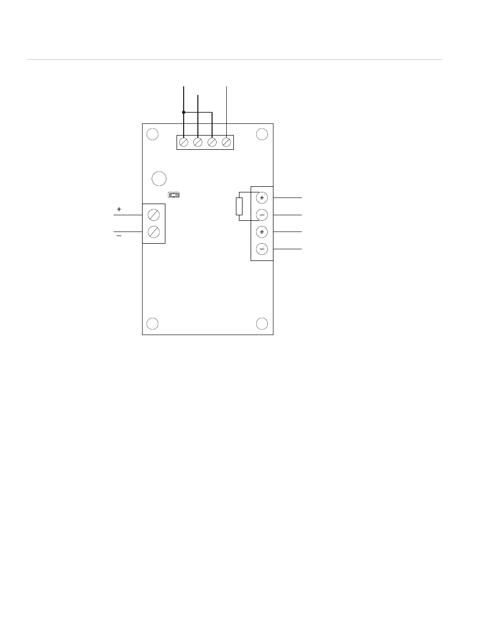
Figure 2: Typical wiring details
(1) LED activates when backup audio is switched in.
(2) Install jumper J1 to eliminate TS1-2 to TS1-4 connection.
(3) Backup amplifier EOLR is required at the ANSBKUP only.
(4) If the primary amplifier is an ANS25, ANS50, or ANS100, turn DIP
switch SN2-5 ON.
If the primary amplifier is an ANS25A, ANS50A, or ANS100A, turn
DIP switch SN1-5 ON.
Speaker
output
From primary amplifier
Input from primary
amplifier (TB1-5 and 6) (4)
Input from backup
amplifier (TB1-5 and 6)
TB2-10
TB3-7
TB2-1
TB1
TS1
TB2
LED (1)
1
2
3
4
J1
1
2
4
3
2
1
(2)
EOLR (3)
See also other documents in the category Edwards Signaling Safety:
- 888D-N5 (3 pages)
- 888D-N5 (4 pages)
- 439D Series (3 pages)
- 101XBRM Series (5 pages)
- 104 GuardSwitch (2 pages)
- 105XBRi Series (5 pages)
- 250-CO (8 pages)
- 111 GuardSwitch (2 pages)
- 113 GuardSwitch (3 pages)
- 124 GuardSwitch (2 pages)
- 125 Class Halogen (4 pages)
- 125 Class Incand (2 pages)
- 125 Class Standard LED (2 pages)
- 125XBR LED (4 pages)
- 125XBRi Chameleon (4 pages)
- 126 GuardSwitch (2 pages)
- 128C GuardSwitch (2 pages)
- 215-F6 GuardSwitch (4 pages)
- 2302 SERIES (2 pages)
- 2315 Series (2 pages)
- 2400 Series (79 pages)
- 251-F6 (4 pages)
- 291-F6 (4 pages)
- 291-F7 (4 pages)
- 300 Series (1 page)
- 300 Series (4 pages)
- 301 (2 pages)
- 302 (2 pages)
- 5530M (8 pages)
- Genesis Signal Master Module (2 pages)
- ADTG4RB (2 pages)
- Genesis Speaker Strobe (4 pages)
- Genesis Remote Mount Signal Master Module (4 pages)
- EBPS Remote Booster Power Supply (64 pages)
- Genesis Temporal Horn (4 pages)
- Genesis Strobe (2 pages)
- Genesis Temporal Horn-Strobe (4 pages)
- Genesis Chime (2 pages)
- Genesis Chime-Strobe (4 pages)
- Genesis Ceiling Speaker (2 pages)
- Genesis Ceiling Strobe (2 pages)
- Genesis High Candela Ceiling Strobe (4 pages)
- Genesis Ceiling Speaker-Strobe (4 pages)
- Genesis High Candela Ceiling Speaker-Strobe (4 pages)
- Genesis Ceiling Horn-Strobe (4 pages)