Edwards Signaling ANSBKUP Backup Amplifier Switcher User Manual
Product description, Specifications, Installation instructions
© 2013 UTC Fire & Security. All rights reserved.
1 / 2
P/N 3101188 • REV 02 • REB 28FEB13
ANSBKUP Backup Amplifier Switcher
Installation Sheet
Product description
The ANSBKUP provides a means to switch to a backup
amplifier in the event of a primary amplifier failure. One backup
amplifier can serve as a backup for several primary amplifiers.
Amplifier outputs are connected at TB2, and speaker field
wiring at TB1. Supervisory and 24 Vdc power inputs are
provided at TS1. The LED activates when the backup amplifier
has been switched in.
All wiring is power-limited.
The ANSBKUP mounts on snap track, or using 5/8-inch nylon
standoffs.
The ANSBUKP is compatible with both 25 Vrms and 70 Vrms
audio signals.
Specifications
Voltage: 24 Vdc
Current
Standby: 40 mA
Active: 10 mA
Installation instructions
The ANSBUKP is mounted in the same cabinet that houses
the primary amplifier. It is designed to be mounted using
standard, 3-inch snap track material.
The board also has mounting holes at the corners for standoff
mounts where necessary. 5/8-inch nylon standoffs are
required.
Terminals and jumpers
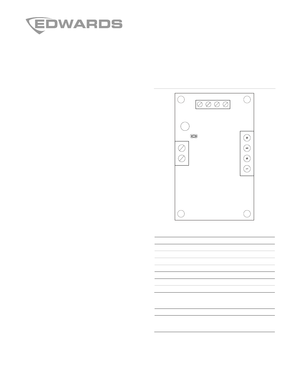
Figure 1 shows the position of the terminal and jumper blocks
on the ANSBKUP. Table 1 describes the terminal assignments,
while Table 2 describes the jumper settings.
Figure 1: Terminal and jumper block positions
Table 1: Terminal descriptions
Terminal
Description
TS1-1
Circuit negative
TS1-2
V+ (24 Vdc)
TS1-3
General purpose input
TS1-4
V+ (24 Vdc)
TB1-1 and 2 Audio output
TB2-1 and 2 Audio input from backup amplifier
TB2-3 and 4 Audio input from primary amplifier
Table 2: Jumper settings
Jumper
Setting
J1
With a jumper on J1-1 and 2, TS1-2 and TS1-4 are
internally connected. An external wire connecting TS1-2
and TS1-4 is not required.
TB1
TS1
TB2
LED
1
2
3
4
J1
1
2
4
3
2
1
Document Outline
- 3101188 R02 Spec
- ANSBKUP Backup Amplifier Switcher Offset Specification
- 3101188 R02 ANSBKUP Backup Amplifier Switcher Installation Sheet