Edwards Signaling Genesis Remote Mount Signal Master Module User Manual
Page 2
2 / 4
P/N 3100299 • REV 07 • REB 30JAN13
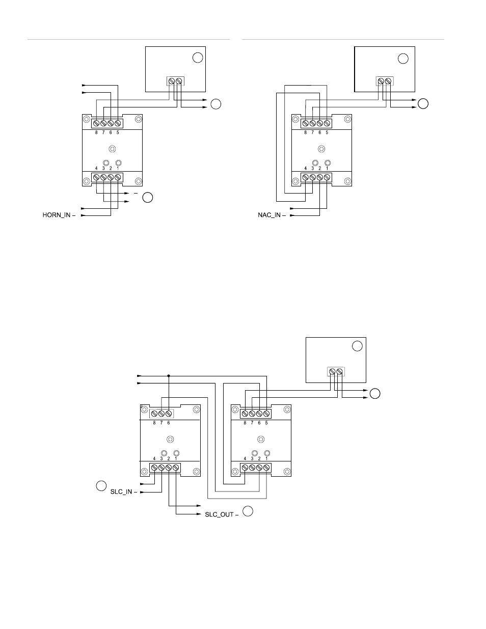
Figure 2: Horn silence / synchronization using two NACs
1.
Strobe or horn/strobe
2.
To next appliance, EOL resistor, or Class A circuit return
3.
To next G1M-RM or end of line resistor
Notes
•
Polarity shown in alarm condition
•
Horn circuit can be silenced without turning off strobes
Figure 4: Synchronization using one NAC
1.
Strobe or horn/strobe
2.
To next appliance, EOL resistor, or Class A circuit return
Notes
•
Polarity shown in alarm condition
•
Horn circuit cannot be silenced without turning off strobes
– +
+
HORN_IN +
1
G1M-RM
STROBE_IN +
STROBE_IN –
2
3
– +
NAC_IN +
1
G1M-RM
2
2
Figure 3: Horn silence / synchronization using one NAC
1.
From previous device or control panel
2. Strobe or horn/strobe
3.
To next appliance, EOL resistor, or Class A circuit return
4.
To next device or Class A circuit return
Notes
•
Polarity shown in alarm condition
•
Horn circuit can be silenced without turning off strobes
•
G1M-RM, CR module, and wire nut must be located in the same enclosure as the Genesis Signal Master.
4
C
NC
– +
CR
SLC_IN +
SLC_OUT +
1
G1M-RM
STROBE_IN +
STROBE_IN –
2
3