Wiring diagram for category 3, Wiring diagram for category 4, General specifications – Edwards Signaling 300 Series User Manual
Page 3
*300-BLT-
( – )
( + )
INT-03-230: 230V AC
INT-03-120: 120V AC
INT-03-024: 24V DC
R e q u i r e d F a s t o r
S l o w - A c t i n g F u s e :
( 2 5 0 V , 5 x 2 0 m m F )
I N T - 0 3 - 2 3 0 : 4 0 m A
I N T - 0 3 - 1 2 0 : 8 0 m A
I N T - 0 3 - 0 2 4 : 1 / 4 A
R e q u i r e d F a s t o r S l o w -
A c t i n g F u s e s : 4 A ( 2 5 0 V ,
5 x 2 0 m m F
W
H
T
B
L
K
R
E
D
B
L
U
*300-BLT-
W
H
T
B
L
K
R
E
D
B
L
U
RESET
A
SAFE
AUX.
B
C
D
Safety Monitor Relay
INT-03
E
F
G
OUTPUTS
230 VAC
60 VDC
120 VAC
30 VDC
LOADS
*300-BLT-
W
H
T
B
L
K
R
E
D
B
L
U
Series Circuit
Parallel
Circuit
–
+
L1
L2 1
2
X1 X2 Y1 Y2
N.O.
N.C.
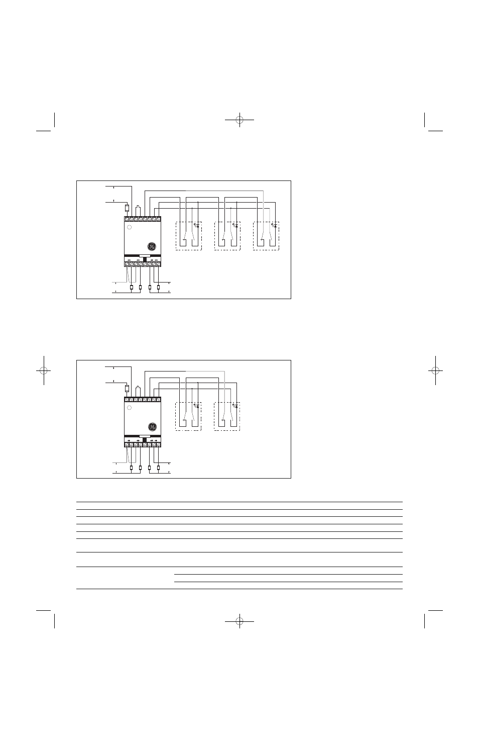
Wiring Diagram for Category 3
Inputs shown with safety gates/guards in closed position.
One Series 300-BT GuardSwitch™ required for each safety gate.
Note:
The LED on the BLT model will be ON
when the guard is open.
Fuses: 1A (250V)
Multiple DPST GuardSwitches: Show with
actuators in position, all guards
closed. The LED of the BLT model will
be on when the guard is open. If
multiple guards are open, LED will
be dimmer. The maximum number
of GuardSwitches that can be used
is 50, although troubleshooting and
line resistance must be considered.
(Do not exceed 30 Ohms of combined
contact and line resistance. Each
GuardSwitch will have less than
0.5 Ohms of resistance.)
*300-BLT-
( – )
( + )
INT-03-230: 230V AC
INT-03-120: 120V AC
INT-03-024: 24V DC
R e q u i r e d F a s t o r
S l o w - A c t i n g F u s e :
( 2 5 0 V , 5 x 2 0 m m F )
I N T - 0 3 - 2 3 0 : 4 0 m A
I N T - 0 3 - 1 2 0 : 8 0 m A
I N T - 0 3 - 0 2 4 : 1 / 4 A
R e q u i r e d F a s t o r
S l o w - A c t i n g
F u s e s : 4 A ( 2 5 0 V ,
5 x 2 0 m m F
W
H
T
B
L
K
R
E
D
B
L
U
*300-BLT-
W
H
T
B
L
K
R
E
D
B
L
U
RESET
A
SAFE
AUX.
B
C
D
Safety Monitor Relay
INT-03
E
F
G
OUTPUTS
230 VAC
60 VDC
120 VAC
30 VDC
LOADS
–
+
L1
L2 1
2
X1 X2 Y1 Y2
N.O.
N.C.
Wiring Diagram for Category 4
Inputs shown with safety gate/guard in closed position.
Two Series 300-BT GuardSwitches™ with one INT relay are required for each safety gate.
When first applying the INT Safety Monitor Relay, the inputs must be cycled to check for proper operation
before the output contacts close. To cycle the inputs, the guard must be opened and closed. This start-up
test is sufficient; however we recommend that the proper operation of the switches and relay be checked
at least every 24 hours.
Note:
The LED on the BLT model will be ON
when the guard is open.
Fuses: 1A (250V)
General Specifications
Enclosure
304 Folded Stainless Steel
Temperature Range
-40°F to 180°F (-40°C to 80°C)
Environmental
Hermetically Sealed Contact Switch Encapsulated in Polyurethane
NEMA Rating
1, 2, 4, 4X, 5, 12, 12K
Protection Class
IP 66
Response Time
1 msec (5.4VA); 10 msec (150VA)
Individual Circuits
The two circuits do not switch simultaneously, and depend on the speed of the guard closure.
Based on closure speed of 1’ per second and a gap of 1/8”, a delay of less than 50 msec is typical.
Life Cycles
100,000 Under Full Load;
Up to 200,000,000 Under Dry Circuit
Lead Types/O.D.
18/4 SJTOW (K)/0.34” (0.86cm)
22/4 PVC Jacketed (J)/0.19” (0.48cm)
22/6 PVC Jacketed (J)/021” (0.53cm)
* Or other DPST GuardSwitch
(See the 300-BT Series installation instructions)
* Or other DPST GuardSwitch
(See the 300-BT Series installation instructions)
Interlock Switches_300 Series.qxd 5/29/08 1:56 PM Page 3