Maintenance, Warnings – Edwards Signaling 125 Class Halogen User Manual
Page 2
P/N 3101650 ISSUE 3
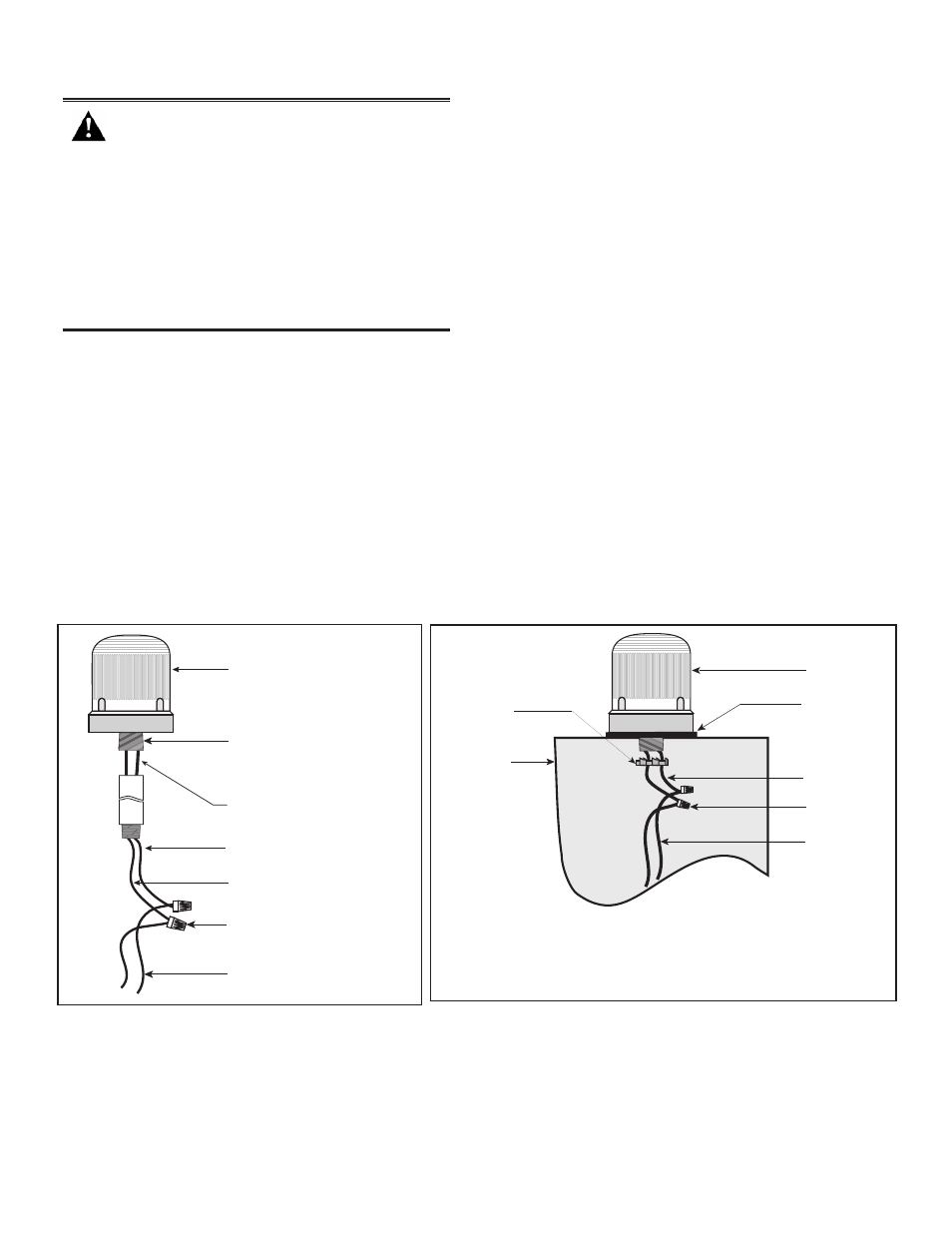
Figure 2. Panel Mounting
125 Class
Visual Indicator
Gasket
(supplied)
Locking Nut -
1.3625" OD
(supplied)
Control panel
(enclosure)
Wire Nuts
(Not Supplied)
18” Wire Leads
Power Source
Wires
Maintenance
Figure 1. Conduit Mounting (3/4" Shown)
To avoid risk of injury, install lens before
energizing the unit.
To avoid the risk of injury, do not start any
maintenance when unit is energized.
To prevent electrical shock, disconnect all
power and wait five (5) minutes for stored
energy in strobe modules to dissipate
before starting work on unit.
WARNINGS
Cleaning
Disconnect power before cleaning. The module lens exterior
surfaces should be periodically cleaned with a soft clean
cloth using water and a mild detergent to maintain optimum
light visibility.
Lamp Replacement
1. Conduit Mounted Modules: Disconnect wiring and, if
necessary, unscrew base from conduit (Figure 1).
Panel Mounted Modules: Disconnect wiring and
remove locking nut that secures the base to the panel
(Figure 2).
2. Remove (4) screws that secure the lens to the base from
bottom of base (Figure 3) and remove lens.
3. Replace halogen lamp as follows (Figure 3):
a. Grasp the metal base of the halogen lamp and push
the lamp down while turning counterclockwise. Then,
pull the lamp directly upward to remove from the
socket.
b. Grasp the new halogen lamp by its base and insert
in the socket. Push down and rotate clockwise to
lock in place.
CAUTION: Do not touch glass surface of lamp at
any time.)
4. Reattach lens to base and fasten with screws removed
in step 2.
125 Class
Visual Indicator
Power Source
Wires
DC units; Red positive (+)
AC units; Black Hot
DC units; Black negative (-)
AC units; White neutral
Wire nuts
(not supplied)
18” Wire Leads
3/4” NPT external (shown)
1/2” NPT internal
conduit (not supplied)