Figure 6. dipswitch settings – Edwards Signaling 101XBRM Series User Manual
Page 5
P/N 3101631 ISSUE 3
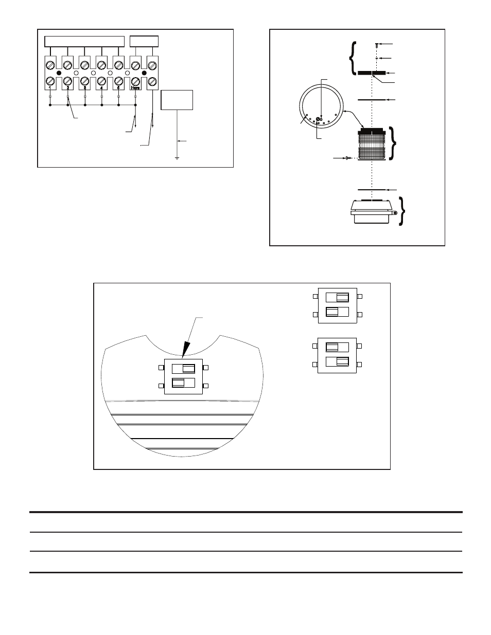
Figure 5. Stacking the Modules on Adapta-
Light Base Unit
Table 3. Specifications
Figure 4. Wiring to the Terminal Block
Median LED
Light
Replacement
Catalog Number
Voltage
Current
Sound Output
Life (L70)
Output
Horn
101BS-N5
120V 50/60 Hz
0.05A
85 dB at 10 ft. (3.05 m)
--
__
123A-N5
101BS-G1
24V DC
need new number
101XBRM*120A
120V 50/60 Hz
0.108A
--
148,000 hr.
†
101XBRM*24D
24V DC
0.215A
--
148,000 hr.
†
*Letter in this position specifies lens and LED color: A - amber, B - blue, G - green, R - red or W - white (lens is clear with white LEDs).
†
Based on LED manufacturer's projections. Refer to http://www.philipslumileds.com/pdfs/WP15.pdf.
Factory installed copper conductors from
terminals 1 thru 5 to contact points.
Factory installed
horn wire leads.
Typical actuating
contact (by others).
(+) for DC,
Hot (line) for AC
(-) for DC,
COM for AC
Connection to
installation ground
Green insulated
ground lead from
120V AC
Adaptalight.
Contacts
Supplied with
Base Unit
Cap screw or
through-bolt
entrance hole
#8-32 x 3/8”
Plastic panhead
screw
#6 x 3/8” Cap
screw
Gasket
Cap
Align notches
for assembly
Gasket
Module
Gasket
Base Unit
Slotted panhead
through-bolt
(Do not remove)
Figure 6. Dipswitch Settings
STEADY
(FACTORY
DEFAULT)
OFF
OFF
ON
ON
1
2
OFF
OFF
ON
ON
1
2
OFF
OFF
ON
ON
1
2
STEADY
65 FPM