Service and maintenance, Pid plug-in sensor maintenance, Figure 14 uv lamp aging expectation – Detcon PI-700 User Manual
Page 33: 1 pid plug-in sensor maintenance
Model PI-700
PI-700 Instruction Manual
Rev. 2.5
Page 29 of 54
5. Service and Maintenance
Calibration Frequency
In most applications, quarterly span calibration intervals will assure reliable detection. However, industrial
environments differ. Upon initial installation and commissioning, close frequency tests should be performed,
weekly to monthly. Test results should be recorded and reviewed to determine a suitable calibration interval.
If, after 180 days, an Auto-Span Calibration is not performed, the ITM will generate an AutoSpan Fault.
5.1 PID Plug-In Sensor Maintenance
The plug-in PID Sensor will need to be properly maintained to achieve proper long-term performance. All
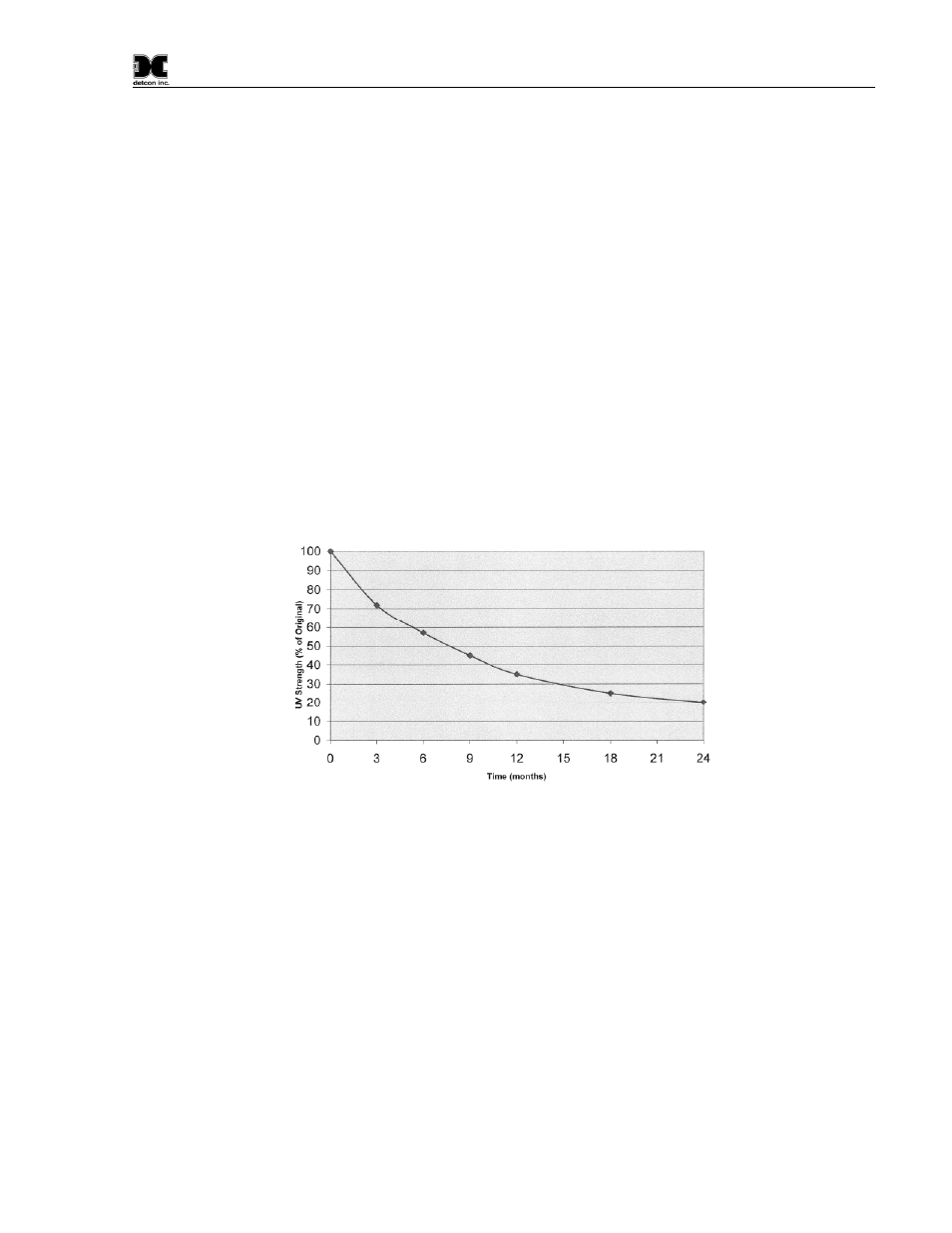
PID sensors use a UV lamp that has a finite lifetime. The Detcon PID UV lamp source is expected to last at
least 1 year. However, from the time of installation a gradual loss in UV lamp strength is expected (Figure
13). As the UV lamp strength decreases the sensor signal will decrease accordingly. This dictates that
periodic span calibrations are required to maintain calibration accuracy. To determine the present signal
strength of the PID sensor execute a valid span calibration and view the Sensor Life from the ‘View Program
Status’ menu. Any Sensor Life value less than 30% should result in the user’s choice of replacing the plug-in
sensor, cleaning the UV Lamp, or replacing the UV Lamp.
Figure 13 UV Lamp Aging Expectation
If the PID sensor appears to be losing signal strength at a rate faster than the estimates shown in Figure 13, the
sensor is most likely experiencing contamination film build-up on the UV optical filter. This will happen
when exposed to certain gases or ambient contaminations that collect on the surface of the UV filter. The
result is a decrease in the amount of emitted UV light from the lamp source. This is known to happen with
gases that can be polymerized by UV light (such as heavy complex VOC’s), airborne oil vapors, and very fine
dust. As UV Filter contamination occurs, the sensor’s signal strength falls off in addition to the expected loss
rate shown in Figure 13. This phenomenon can be reversed by disassembling the sensor and carefully cleaning
the UV lamp filter using a specialized cloth.
A secondary filter accessory, built into the splashguard adapter, is used with the Model 700 PID sensors
(Figure 14). This multi-stage filter is designed to prevent heavy and complex airborne VOC molecules from
contacting the PID sensor and causing surface contamination and subsequent reading drift. When used
effectively, it may extend the time between required sensor cleaning and / or sensor replacement. Its use is
limited to application cases where the target gas(s) are moderate to small VOC molecules (i.e. benzene and
smaller molecular weights). Before installing, it must be verified that the filter does not inhibit response to the
target gas being monitored. Do not use this filter if the target gas response is inhibited. The service life of the