Field wiring, Figure 8 typical installation, Figure 8 – Detcon PI-700 User Manual
Page 12: 6 field wiring
Model PI-700
PI-700 Instruction Manual
Rev. 2.5
Page 8 of 54
NOTE: The Detcon Warranty does not cover water damage resulting from water leaking into
the enclosure. Since the electronics are 100% epoxy encapsulated, only the wire terminations
can get wet. This could cause abnormal operation and possibly cause corrosion to the terminal
connections. However, it would not be expected to cause permanent damage to the sensor.
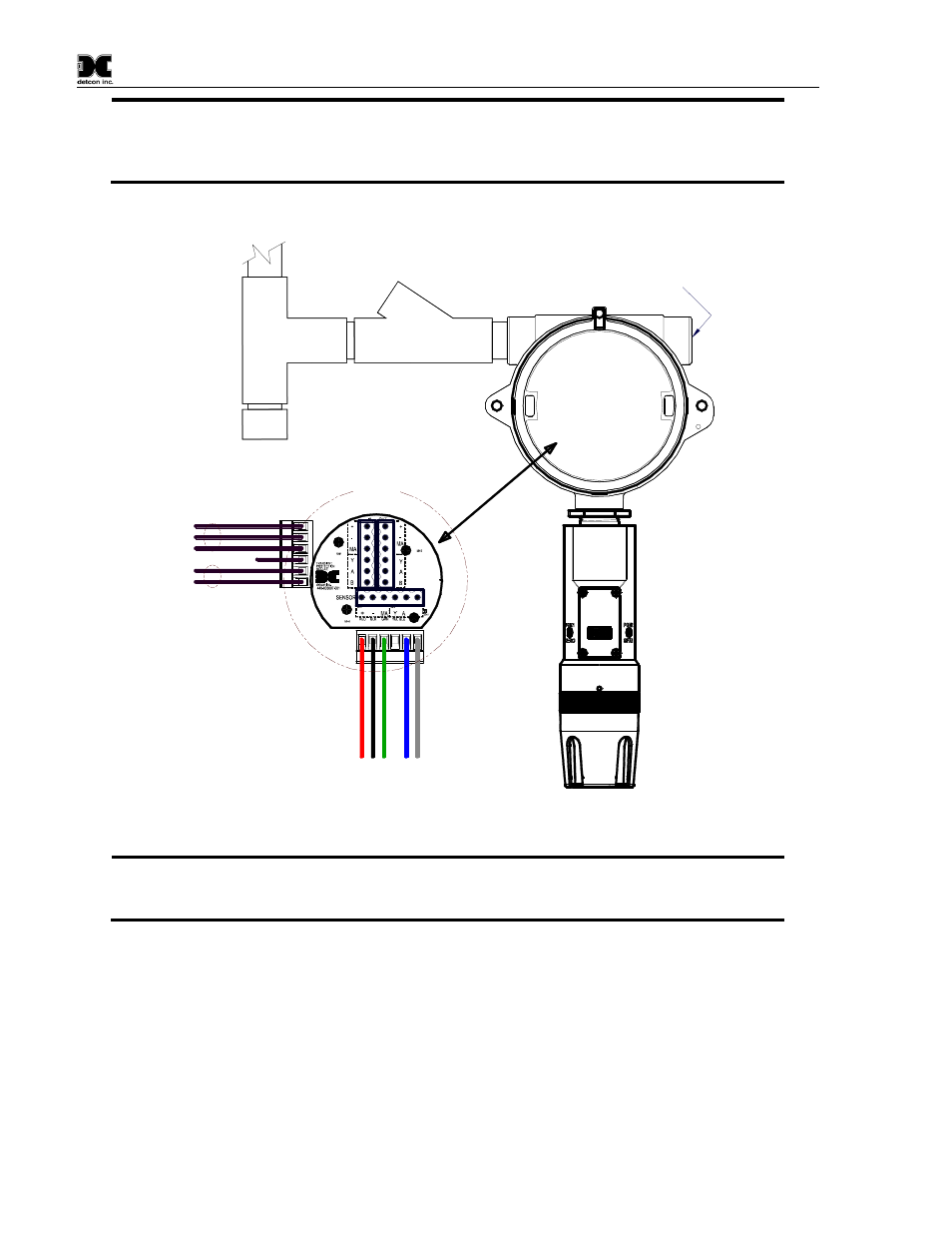
Plug any unused
ports
Explosion Proof
Housing
(J-Box)
Drain
DM-700
Sensor
Assembly
Conduit
"T"
EYS Seal Fitting
MODEL
PI-700
detcon inc.
VOC
(+
)
m
A
(-
)
A
(+
)
B
(-
)
Wiring to
Sensor Assembly
W
h
t
B
lu
R
e
d
G
rn
B
lk
Explosion
Proof
Junction Box
(+)
mA
(-)
N/U
A(+)
B(-)
Customer
Supplied Wiring
Transient Protection Module
(TPM) P/N 500-003087-100
Mount TPM in Explosion
Proof Enclosure to ground
unit properly. Mount to
bottom of enclosure using
6-32 screws.
6-Pin Pheonix Plug
P/N 306-175705-100
Figure 8 Typical Installation
NOTE: Any unused ports should be blocked with suitable ¾” male NPT plugs.
Detcon
supplies one ¾” NPT male plug with their accessory J-box enclosures. If connections are other
than ¾” NPT, use an appropriate male plug of like construction material.
2.6 Field Wiring
Detcon Model PI-700 toxic gas sensors assemblies require three conductor connections between power
supplies and host electronic controller’s 4-20mA output, and two conductor connections for the Modbus™ RS-
485 serial interface. Wiring designations are + (DC), – (DC), mA (sensor signal), and Modbus™ RS-485 A
(+), and B (-). Maximum wire length between sensor and 24VDC source is shown in the Table 1 below.
Maximum wire size for termination in the Detcon J-Box accessory is 14 gauge.