Aquametrix 2200C Conductivity Controller User Manual User Manual
Page 25
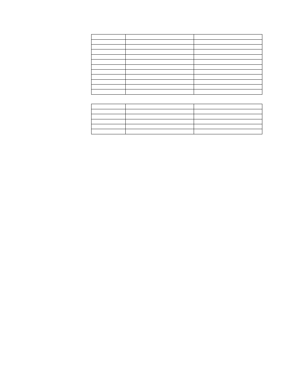
Range uS
Required Cell Constant
R68 Value
0-2uS
0.01
10,000
0-5 uS
0.01
4000
0-10 uS
0.05
10000
0-20 uS
0.05
5000
0-50 uS
0.05
2000
0-100 uS
0.05
1000
0-200 uS
0.5
5000
0-500 uS
0.5
2000
0-1000 uS
0.5
1000
0-2000 uS
1.0
1000
0-5000 uS
1.0
400
Range mS Required Cell Constant
R68 Value
0-10 mS
10
2000
0-20 mS
10
1000
0-50 mS
10
400
0-500 mS
50
200
0-1000 mS
50
100
c) Set the temperature simulation DIP switch No. 1, S43 ON and Switch No. 2
OFF. This is to simulate 25°C. Set the conductivity simulation DIP switch No. 1,
S44 ON and switch No. 2 OFF. The display should indicate mid-range ±5%.
(For example, for range 5000 µS, cell constant is 1 and R68 = 400 Ohms
display should be 2500 µS ±5%.)
d) Now set the conductivity simulation DIP switch No. 1, S44 OFF and switch No.
2 ON. The display should show full range ±5%.
NOTE: Do not use this mode for calibration if both c) and d) are satisfied the
analyzer is in order and the problem is with the probe.
9.2 Escape
9.2.1
If the instrument appears to be "DEAD", for example not responding to the buttons,
or not performing on line measurement and control, always try the reset feature first,
as described in 6.3.1.
9.2.2
a) The "ESCAPE" procedure is to be used normally at the factory only, when the
unit is powered with a new processor. As a result, the internal non-volatile
memory (EPROM) is "FORMATTED" and the factory values are loaded into it.