Aquametrix 2200C Conductivity Controller User Manual User Manual
Page 17
main circuit board, in the up position, (this places a 3000 ohm across the RD and
GN terminals) the temperature should read 25°C or 77°F.
5.10.2 The 0-5 Vdc and 0-1 mA analog outputs can be dedicated to follow the process
temperature by simply placing DIP switch No. 8 of Bank S1. in the OFF position.
The temperature span of the output is set to the utility menu. Refer to Section 7.4.
5.11 Status
5.11.1 The 2200C continuously checks the integrity of all stored data and monitors the
condition of the measuring system. If a fault is detected, the FAIL LED above the
display will turn red. The STATUS in the operation menu will provide a numerical
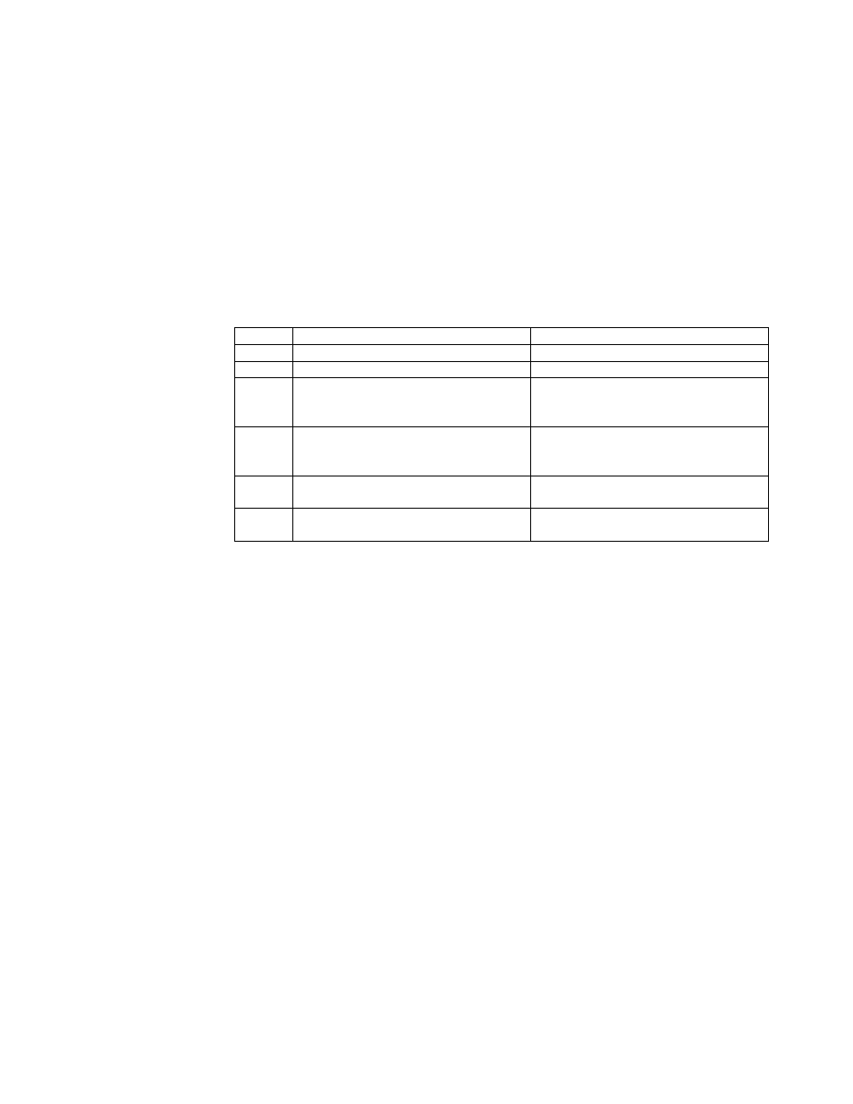
code, giving a possible cause and a suggested remedy.
CODE POSSIBLE CAUSE
SUGGESTED REMEDY
0
Normal Condition
No action required
1
Reserved
2
Temperature Sensor off Scale
Check for open or short
connections of temperature sensor
input (Terminals RD & GN on TB2)
3
Conductivity reading off Scale
Verify process. Check for open or
short connections. WH and BL
wires
4*
Memory Loss
Call your AquaMetrix Rep. Or
Water Analytics directly
5
Calibration out of limit
Check scale setting (See range
change in Utility Menu)
NOTE: Code 4 could be a serious failure so the alarm relay will activate in addition to the red
illumination of the FAIL LED if Dip Switch No. 5 of Bank S1 is off.
5.12 Range
5.12.1 This menu item is read only, it displays the maximum range of the instrument as
currently configured. You may change the range in the Utility Menu. Refer to
Section 7.3.
5.13 Cell Constant
5.13.1 This menu item is read only, it displays the cell constant required for the range, as it
is currently configured.
6.0
OPERATING HINTS
6.1 Cell Care
6.1.1
Keep the cell clean using the procedure recommended in the cell manual. The
frequency of cleaning depends on the solution being monitored.