Triton RT2000 X2 Installation Manual User Manual
Page 31
31
M
ODEL
RT2000 (X2) I
NSTALLATION
G
UIDE
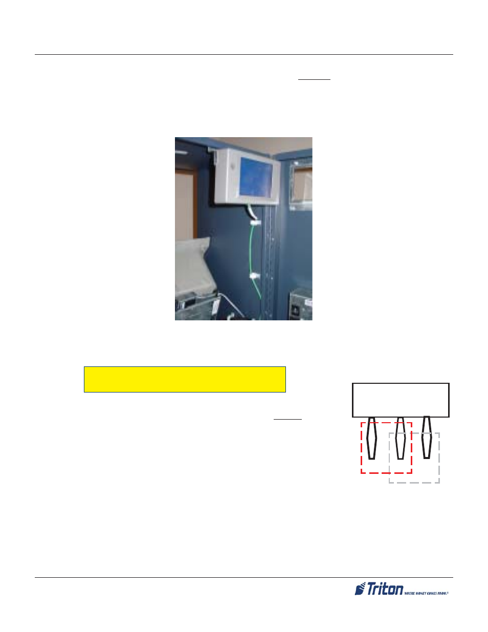
4. Mount the OSP so that the data cable will be connected on the bottom of the panel.
5. Connect the Data cable (RJ-45 connector end) to the OSP shown in Figure 3. Ensure the other end of
cable is connected to the
“A
UXILLARY
” port on the Docking board.
Figure 3. OSP mounted and cable connected.
12V
DTR
J11
IMPORTANT: The Rear Operator Service Panel (OSP) MUST have a
jumper set on the Docking Board. The jumper ( ‘J11’ on the Docking
Board) must be set to “12V”. See graphic at right.
C
ONFIGURE
D
OCKING
B
OARD
J
UMPER
:$51,1*
Inspect the Mounting Bracket Studs and RSP Mounting Holes closely. Note the studs
have grooves provided for the RSP to mount onto. Ensure the RSP sets down onto the
studs properly on all 3 (three) mounting points. Failure to do so may allow the RSP to
become dislodged, which may cause physical and electrical damage to the RSP and
possibly personal injury.
- X-SCALE/X2 Configuration Manual (419 pages)
- ARGO Installation Manual (35 pages)
- ARGO User Manual (97 pages)
- ARGO G60 Installation Manual (31 pages)
- ARGO Quick Reference Guide (10 pages)
- RL331X TRAVERSE User Manual (74 pages)
- FT5000 X2 User Manual (105 pages)
- FT5000 X2 Quick Reference Guide (10 pages)
- 81XX/91XX (including X2)/97XX/RL16XX (5 pages)
- RL1600 Installation Manual (41 pages)
- RL1600 Quick Reference Guide (7 pages)
- RL1600 User Manual (72 pages)
- RL2000 POWER CORD Installation Manual (1 page)
- RL2000 User Manual (124 pages)
- RL2000 Installation Manual (45 pages)
- RL2000 Quick Reference Guide (10 pages)
- RL5000 X2 Series User Manual (122 pages)
- RL5000 X2 Series Installation Manual (55 pages)
- RL5000 X2 Series Quick Reference Guide (12 pages)
- 8100/9100/97XX/RL5000 (X-SCALE/XP) (10 pages)
- 8100 Quick Reference Guide (6 pages)
- 8100 User/Installation Manual (150 pages)
- 9100 Installation Manual (50 pages)
- 9100 Quick Reference Guide (8 pages)
- 9100 User Manual (172 pages)
- 9100 Electronic Lock Installation Manual (8 pages)
- 96XX CASH DISPENSER CABINET Installation Manual (6 pages)
- 9650 Operation Manual (264 pages)
- 9600 Series Quick Reference Guide (2 pages)
- 9640 Operation Manual (265 pages)
- 9600 Operation Manual (209 pages)
- 9610 Series Quick Reference Guide (2 pages)
- 9610 Operation Manual (210 pages)
- 97XX Series Operation Manual (265 pages)
- 9710 Series Quick Reference Guide (2 pages)
- 9700 Series Quick Reference Guide (2 pages)
- 9705 Series Quick Reference Guide (2 pages)
- 9200 Installation Manual (26 pages)
- 9200 Operation Manual (179 pages)
- MAKO 2000 Operation Manual (217 pages)
- MAKO PEDESTAL Installation Manual (8 pages)
- MAKO EXTENDED CABINET Installation Manual (7 pages)
- RT2000 X2 User Manual (109 pages)
- RT2000 X2 Quick Reference Guide (8 pages)