Chart e, Reassembly – Star Water Systems CJ101 (Flint & Walling) User Manual
Page 5
8
95 North Oak Street • Kendallville, IN 46755 • Copyright © 2012. All rights reserved.
9
95 North Oak Street • Kendallville, IN 46755 • Copyright © 2012. All rights reserved.
PRIMING
1. Before starting any centrifugal pump, it is
absolutely necessary that both the casing and
suction pipe be completely filled with liquid.
This priming can be accomplished by any of
the following methods:
2. When the liquid supply level is above the center
line of the pump, it is primed by opening the
suction and discharge valves. The inflowing
liquid will displace the air and fill the suction
line, pump casing, and discharge line up to the
level of supply.
3. Where the pump is operating with suction
lift and the suction line is equipped with a
foot valve, remove the priming plug from the
discharge tee (see Figures 5-8) and fill the
pump body and suction pipe completely with
water. No additional water will be needed for
subsequent start-ups unless the pump body is
drained.
4. After the pump is turned on it will require 2-5
minutes before all air is evacuated from the
suction line and water begins to flow. If there
is no water after 5 minutes, turn the pump off
and check the following:
5. Any air leaks on the suction line must be
eliminated.
6. Suction pipe inlet should be a minimum of 5
feet below the water level.
7. Total suction lift cannot be greater than 25 feet.
8. Any restrictions in the discharge pipe, such as a
closed valve must be eliminated.
NOTE: Unit must be full of liquid before operating.
Never run dry, or against a closed discharge. Dry
running or running unit against a closed discharge
will cause damage to the shaft seal. Do not pump
dirty water or abrasive liquids, otherwise the same
may occur as if running dry.
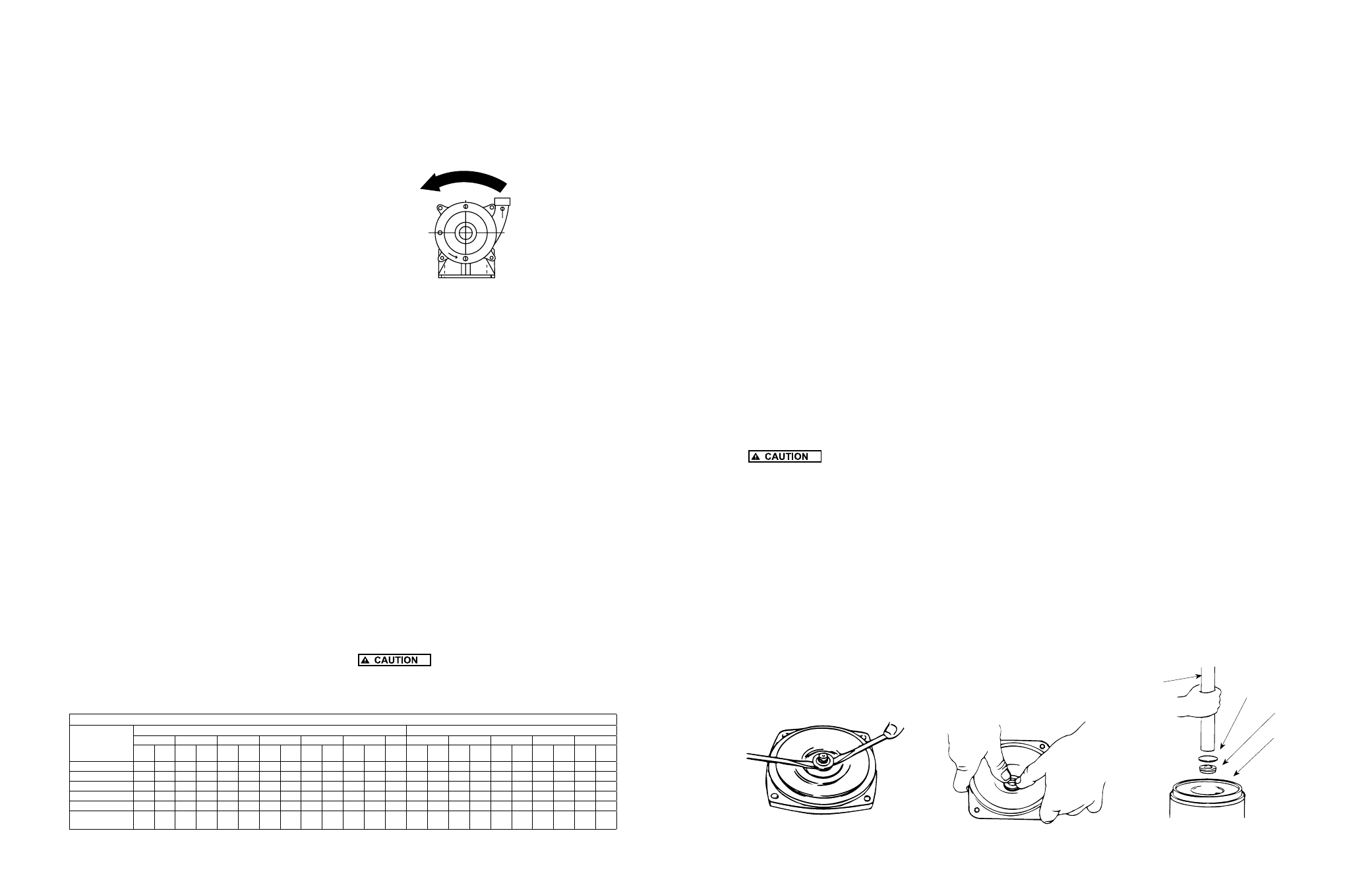
MOTOR ROTATION
1. Single phase models are one (1) rotation only
(counterclockwise when facing the pump
suction tapping) and cannot be reversed.
2. Proper rotation of pump impeller is critical for
three phase pumps. Pump motor should turn
counterclockwise (CCW) when facing pump
suction tapping. Momentarily “bump” (apply
power for less than a second) the motor to check
for proper rotation. To change rotation on three
phase units, interchange any two (2) incoming
line (power) leads.
IL0416
Figure 14 - Correct Motor Rotation
MAINTENANCE
Lubrication
The pumps and motors require no lubrication.
The ball bearings of the motor have been greased
at the factory. Under normal operating conditions
they should require no further greasing.
Winterizing your Pump
Cracked pump housings caused by freezing are
not covered by warranty. To protect your pump
from freezing, for best results remove the pump
and store in a warm environment. If pump cannot
be removed from your system, remove both
drain plugs, one on the suction flange and one
at the bottom rear of the pump (see fig 2 in the
instructions.) Allow the water to completely drain
from the pump. Re-install both drain plugs and fill
pump with RV type antifreeze. Antifreeze also acts
as a rust inhibitor. It will help keep rust build up to
a minimum and seals lubricated inside the pump
while it is not in use.
ROTARY SEAL ASSEMBLY REPLACEMENT
Disassembly
When disassembling the pump, care
should be taken not to damage the gaskets. If torn or
Chart E
MINIMUM COPPER WIRE SIZE CHART (GAUGE)
DISTANCE FROM
MOTOR TO FUSE
BOX METER,
OR ELECTRICAL
OUTLET
SINGLE PHASE MOTORS
THREE PHASE MOTORS
1/3 HP
1/2 HP
3/4 HP
1 HP
1-1/2 HP
2 HP
3 HP
3/4 HP
1 HP
1-1/2 HP
2 HP
3 HP
115V 230V 115V 230V 115V 230V 115V 230V 115V 230V 115V 230V 230V 230V 460V 230V 460V 230V 460V 230V 460V 230V 460V
0-50’
14
14
12
14
12
14
10
14
10
12
10
12
10
14
14
14
14
14
14
14
14
14
14
50-100’
14
14
12
14
12
14
10
14
8
12
8
12
10
14
14
14
14
14
14
14
14
14
14
100-150’
14
14
12
14
10
14
10
12
6
12
6
12
10
14
14
14
14
14
14
14
14
14
14
150-200’
12
14
12
14
10
12
8
12
*
10
*
10
10
14
14
14
14
12
14
12
14
12
14
200-300’
12
14
10
14
8
12
6
10
*
10
*
10
8
14
14
12
14
12
14
10
12
10
12
Breaker Size
(Amps)
15
15
20
15
20
15
30
15
30
20
30
20
30
15
15
15
15
15
15
15
15
15
15
(*) Not economical to run in 115 volt, use 230 volts
damaged, replace with new gasket (see parts list).
1. Remove the four (4) pump through bolts that
connect the mounting ring to the pump body.
Remove the pump body, taking care not to
damage the gasket or o-ring.
2. Remove the impellers. CJ103 Models are
single stage units, having one impeller. Using
a 9/16” open end wrench, hold the motor shaft
flat and unthread the impeller by turning it
counterclockwise. The motor shaft flat area is
located in the middle of the mounting ring.
3. CJ101 models are multi stage units, having
two or more impellers and one or more
intermediate stages. Using an 11/16” open
end wrench on the motor shaft extension
flat, remove the first impeller by turning or
counterclockwise. Remove the intermediate
stage (stages) taking care not to damage the
gasket (gaskets) and unthread the remaining
impellers.
4. Remove the mechanical seal assembly. The
rotary portion of the seal assembly (carbon
ring, Buna-N gasket and spring) will easily slide
off the end of the shaft. The ceramic portion
can be pried out of the rubber seating using
two (2) screwdrivers (see Figure 15).
Reassembly
The precision lapped faces of the
mechanical seal are easily damaged. Handle the
replacement seal carefully. Short seal life will result if
seal faces (ceramic & carbon) are nicked, scratched or
dirty.
1. Clean the seal cavity of the mounting ring and
the motor shaft thoroughly.
2. Apply liquid soap (one drop only) to the outside
of the Buna-N gasket that houses the ceramic
seal seat. With thumb pressure, press the
ceramic seat, polished face up, squarely into
the seal cavity (see Figure 16).
3. If seal does not seat squarely, remove and
reclean the seal cavity. Place a cardboard
washer over the polished seal face and carefully
press into place using a piece of pipe or tubing
(see Figure 17). Discard cardboard washer.
4. Apply liquid soap (one drop only) to the inside
diameter of the rubber drive ring. Slip rubber
drive ring (carbon face down) and the spring
over the shaft.
5. Reassemble the pump by following the reverse
order of the disassembly instructions.
MOTOR REPLACEMENT
1. Nema J motors can be replaced in the field
with any standard Nema J jet pump motor by
referring to the following instructions and the
attached parts list.
2. Follow steps as outlined under Rotary Seal
Replacement to remove the pump body,
diffuser, impeller and rotary seal.
3. Remove bolts that connect the motor to the
mounting ring and pull motor away.
4. Replace motor with standard Nema J jet
pump motor by positioning motor against the
mounting frame and assembling with four (4)
3/8” x 3/4” cap screws. The mounting base is
connected at the bottom of the mounting frame
with two (2) 3/8” x 1/2” cap screws.
5. Follow steps of Rotary Seal Assembly to
reassemble the remainder of the pump.
BECAUSE DAMAGE TO THE SHAFT SEAL IS
MOST LIKELY TO OCCUR IN DISASSEMBLY, A
NEW SEAL WILL BE NECESSARY.
Figure 15 - Remove Mechanical Seal
Figure 16 - Press in Seal
Figure 17- If Necessary, Press with
Cardboard and Pipe
IL0173
IL0168
IL0169
3/4” Pipe
- Press
Carefully
NOTE:
Cardboard Washer
Protects Seal Face
Seal
Seal
Cavity