Typical installations, Cj101 series chart b, Motor data chart c – Star Water Systems CJ101 (Flint & Walling) User Manual
Page 2: Dimensions (in inches) cj103 series chart a
2
95 North Oak Street • Kendallville, IN 46755 • Copyright © 2012. All rights reserved.
3
95 North Oak Street • Kendallville, IN 46755 • Copyright © 2012. All rights reserved.
IL0396
H
A
C
J
E
D
F
K
B
G
IL0395
F
H
A
C
D
E
J
B
G
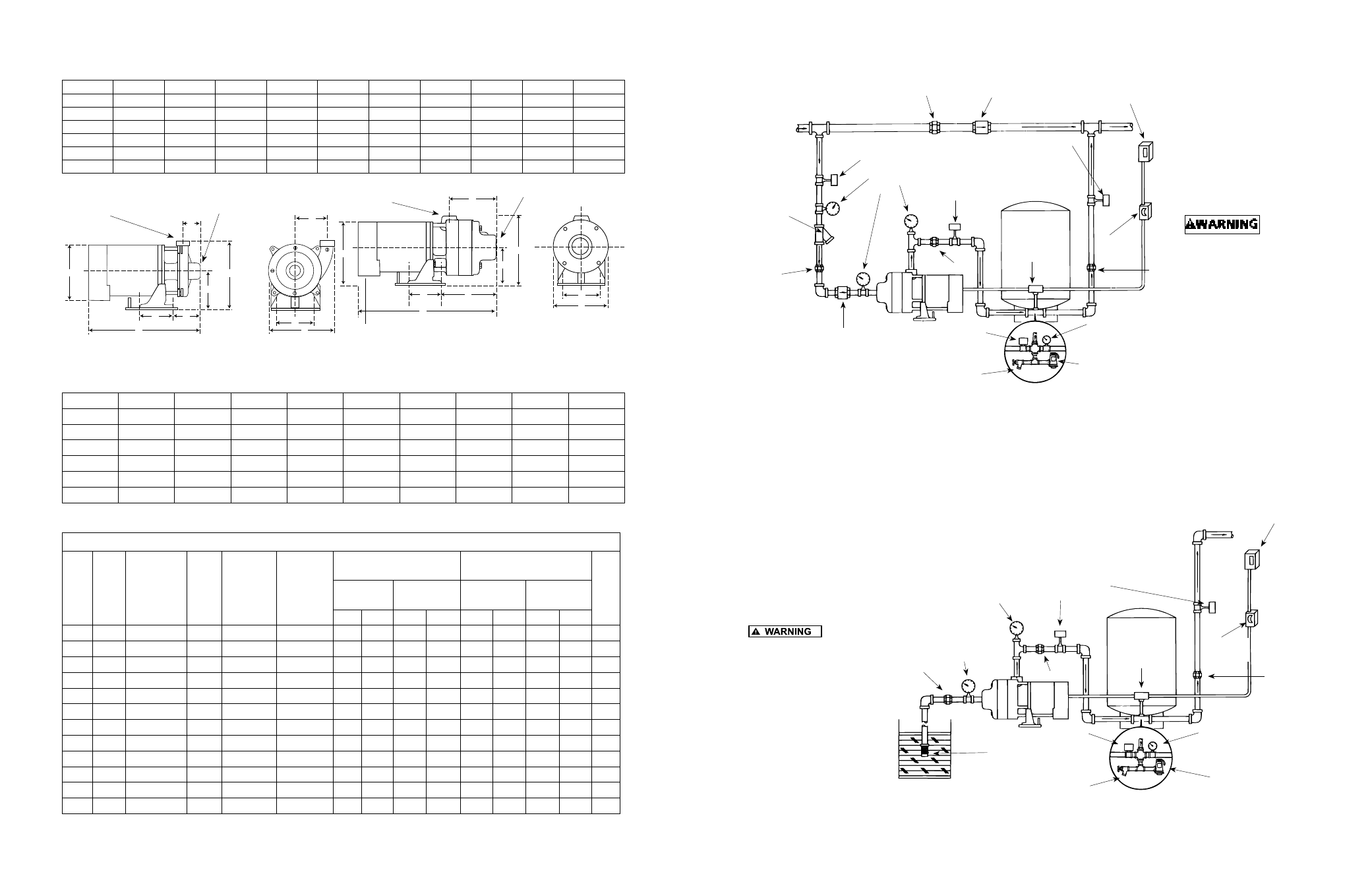
Figure 3 - CJ103 Single Stage Booster Pump
Figure 4 - CJ101B Two and Three Stage Booster Pump
1-1/4” Discharge
1-1/2” Suction
IL0413
IL0414
Figure 5
Figure 6
To size pressure tank
properly, match the
drawdown of the tank
to the capacity of the
pump.
(*) For manual
operation, omit the
pressure tank and
pressure switch. Wire
motor direct to fuse
box.
Install
a pressure relief valve
on any installation
where pump pressure
can exceed the pressure
tank’s maximum working
pressure or on systems
where the discharge
line can be shut off or
obstructed. Extreme
over pressure can result
in personal injury or
property damage.
Gate/Ball Valve
(Normally Open)
Check Valve
Union
Line Strainer
or Filter
(Optional)
Street Supply
Union
Gate/Ball Valve
(Normally Open)
Pressure
Gauge
Check Valve
Union
Gate/Ball Valve
(Normally Open)
Pressure Tank
Pressure
Switch
Main Power Box
Fuse Box
or Switch
Union
Pressure Switch
Drain
Pressure Gauge
Pressure Relief Valve
Foot Valve
with Strainer
Pressure Tank
Pressure
Switch
Pressure
Gauge
Main Power Box
Gate/Ball Valve
(Normally Open)
Fuse Box
or Switch
Union
Pressure Switch
Drain
Pressure Gauge
Union
Pressure Relief Valve
Vacuum
Gauge
Union
Typical Installations
1-1/4” Discharge
1-1/2” Suction
CJ101 Series
Chart B
HP
A
B
C
D
E
F
G
H
J
3/4
4
4-5/8
7-9/16
4-13/16
8-3/4
6-1/4
7
8-1/8
17-7/8
1
4
4-5/8
7-9/16
4-13/16
8-3/4
6-1/4
7
8-1/8
18-3/8
1-1/2
4
4-5/8
7-9/16
4-13/16
8-3/4
6-1/4
7
8-1/8
19
2
4
4-5/8
7-9/16
4-13/16
8-3/4
6-1/4
7
8-1/8
19-1/2
2 *
4
4-5/8
9-7/16
4-13/16
8-3/4
8-1/8
7
8-1/8
21-3/8
3 *
4
4-5/8
9-7/16
4-13/16
8-3/4
8-1/8
7
8-1/8
21-3/8
(*) Three Stage
Motor Data Chart C
HP
PH
VOLTS
HZ
RPM
MOTOR
VOLTAGE
(FACTORY)
CONNECT.
SERVICE FACTOR MOTOR
AMPS
LOCKED ROTOR AMPS
KVA
SINGLE
PHASE
THREE
PHASE
SINGLE
PHASE
THREE
PHASE
115V 230V
230V
460V
115V
230V
230V
460V
1/3
1
115/230
60
3450
115V
8.6
4.3
—
—
26.0
13.0
—
—
K
1/2
1
115/230
60
3450
115V
13.0
6.5
—
—
36.0
18.0
—
—
K
3/4
1
115/230
60
3450
230V
14.0
7.0
—
—
52.0
26.0
—
—
K
1
1
115/230
60
3450
230V
18.0
9.0
—
—
70.0
39.0
—
—
L
1-1/2
1
115/230
60
3450
230V
21.0
10.5
—
—
98.0
49.0
—
—
J
2
1
115/230
60
3450
230V
25.0
12.5
—
—
116.0
58.0
—
—
H
3
1
230
60
3450
230V
—
13.5
—
—
—
53.0
—
—
D
3/4
3
208-230/460
60/50
3450/2850
230V
—
—
3.5
1.75
—
—
19.0
9.5
K
1
3
208-230/460
60/50
3450/2850
230V
—
—
4.5
2.25
—
—
26.9
13.5
K
1-1/2
3
208-230/460
60/50
3450/2850
230V
—
—
5.7
2.85
—
—
33.5
16.8
K
2
3
208-230/460
60/50
3450/2850
230V
—
—
7.4
3.0
—
—
44.0
22.0
K
3
3
208-230/460
60
3450
230V
—
—
9.8
4.9
—
—
48.0
24.0
D
Dimensions (In Inches) CJ103 Series
Chart A
HP
A
B
C
D
E
F
G
H
J
K
1/3
4
4-5/8
3-11/16
4-13/16
9-3/16
2-1/2
8-1/4
8-1/8
13-1/4
3-7/8
1/2
4
4-5/8
3-11/16
4-13/16
9-3/16
2-1/8
8-1/4
8-1/8
13-1/2
3-7/8
3/4
4
4-5/8
3-11/16
4-13/16
9-3/16
2-1/8
8-1/4
8-1/8
14
3-7/8
1
4
4-5/8
3-11/16
4-13/16
9-3/16
2-1/8
8-1/4
8-1/8
14-1/2
3-7/8
1-1/2
4
4-5/8
3-11/16
4-13/16
9-3/16
2-1/8
8-1/4
8-1/8
15-1/8
3-7/8
2
4
4-5/8
3-11/16
4-13/16
9-3/16
2-1/8
8-1/4
8-1/8
15-5/8
3-7/8