Pump performance chart d – Star Water Systems CJ101 (Flint & Walling) User Manual
Page 3
4
95 North Oak Street • Kendallville, IN 46755 • Copyright © 2012. All rights reserved.
5
95 North Oak Street • Kendallville, IN 46755 • Copyright © 2012. All rights reserved.
Practical Suction Lifts at Various Elevations and
Water Temperatures in Degrees Fahrenheit
Altitude
60º
80º
100º 120º 140º 160º 180º 200º
Sea Level -22
-21
-20
-18
-15
-10
-4
+5
2000
-20
-19
-18
-16
-12
-7
-1
+8
4000
-17
-16
-15
-13
-10
-4
+2
+12
6000
-15
-14
-13
-11
-7
-2
+6
+16
8000
-13
-12
-10
-8
-4
+2
+9
—
10000
-10
-9
-8
-6
-2
+4
+13
—
This table gives the maximum permissible suction lift or
the minimum head permitted on the suction side of a pump
at various altitudes and liquid temperatures. A minus sign
before a number indicates suction lift. A plus sign before a
number indicates minimum head. These figures are to be
used as a guide.
PIPING
1. Use galvanized piping, rigid plastic or other
suitable pipe that will not collapse under
suction or rupture due to pressure.
2. The diameter of the suction and discharge pipe
should be no smaller than the corresponding
tappings of the pump (see Figure 3 & 4). If long
runs are encountered larger pipe should be
used. Smaller pipe will reduce the capacity of
the pump.
3. All joints and connections should have Teflon
tape or pipe sealing compound (male threads
only) applied and drawn up tightly.
The entire system must be air and
water tight for efficient operation.
PUMP INSTALLATION
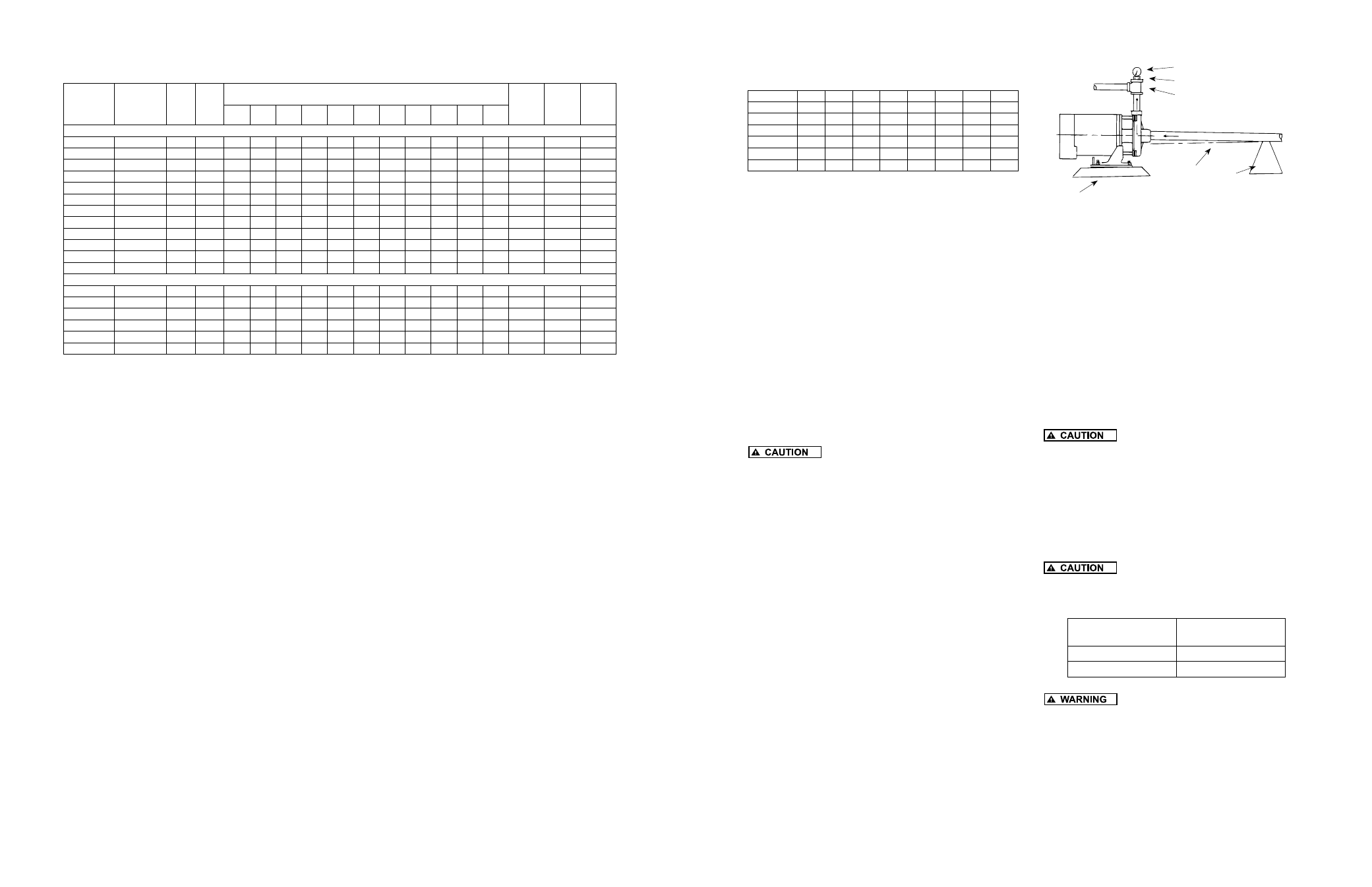
Refer to Figures 5, 6, and 7 for typical installations.
Both the suction and discharge pipe should be
supported at a point near the pump to avoid
strains being placed on the pump.
1. If the pump is used as part of a permanent
installation, secure to a rigid foundation with
appropriate fasteners.
2. Locate the pump as close to the water as
possible, keeping the suction pipe as short as
conditions permit.
3. Avoid dips or pockets in offset piping or air
will accumulate at high points which will make
priming difficult.
4. The suction pipe should slope upward to the
pump inlet. A horizontal suction line must have
a gradual rise to the pump.
Pressure Gauge
Rigid
Foundation
Priming Plug
Level
Pipe
Support
Discharge Tee
Suction Pipe Installed with
Gradual Rise to Pump Inlet
Figure 7
5. On suction lift installations, a foot valve located
in the water or a check valve located as close
to the water as possible will reduce priming
time of the pump and help maintain prime. A
strainer must be used on the suction line to
filter out dirt and debris.
6. A priming tee installed in the pump discharge
port allows water to be poured into the pump
case and suction piping, which is required for
priming on suction lift installations.
7. Install a gate valve and union in the suction and
discharge lines. For removal of the pump for
service, close the gate valve and disconnect the
union.
Do not use a globe valve or other
restricting type of valve at the discharge. This will
seriously restrict the capacity of the pump.
8. Pressure Gauges - Properly sized vacuum or
pressure gauges can be installed in both the
suction and discharge pipe. The gauges will
enable observation of the pump’s performance
as well as detecting cavitation, vapor binding or
other unstable operation.
Use only components that are rated
higher than shut-off pressure of the system. Do not
exceed the pump’s maximum case pressure as listed in
the following table.
Models
Maximum Case
Pressure
CJ103
100 PSI
CJ101
160 PSI
A pressure relief valve of adequate
capacity must be installed on any installation where
the pump pressure can exceed the pressure tank’s
maximum working pressure or on systems where
the discharge line can be shut-off or obstructed.
Not providing a relief valve can cause extreme over
pressure which could result in personal injury and/or
property damage.
INSPECTION AND STORAGE
When unpacking the unit, inspect carefully for any
damage that may have occurred during shipment.
If the unit is received sometime before it can be
used, it should be inspected, recrated and stored
in a dry location.
LOCATION
IMPORTANT: In installations where property
damage might result from an inoperative or
leaking pump due to power outages, discharge
line blockage or any other reason, a back-up
system (s) and/or warning system (s) should be
used.Install a gate valve and union in the suction
and discharge lines. For removal of the pump for
service, close the gate valve and disconnect the
union.
1. Locate pump as close to the fluid source as
possible.
2. Place unit where the motor electrical
components and piping are protected from the
weather and extremes of heat, humidity and
below freezing temperatures.
3. Mount unit in a dry location that is easily
accessible for inspection and maintenance. If
a dry location is not available, mount it on a
foundation well above the wet floor.
4. Allow ample clearance around unit for free air
circulation.
5. CJ103 Series pumps incorporate a discharge
port on the pump casing that can be adjusted
in 90 increments. If necessary, adjust the
discharge port to accommodate the specific
application. Pump performance will not be
affected by the position of the discharge port.
SUCTION LIMITATIONS
1. Units are non self-priming. Normally after
being primed the total suction lift of the pump
is 25 feet. Suction lift varies depending upon
elevation (altitude) and water temperature. See
Practical Suction Lift chart.
2. Where liquids at or near their boiling points
are being handled, the supply must be located
above the suction, so that the available NPSH
will be greater than that required by the unit.
Pump Performance
Chart D
To convert to feet of head, multiply by 2.31.
* Operation of pump in this range may result in m otor damage.
Do not exceed the maximum case pressure and maximum liquid temperature rating of the pump.
Suction & Discharge Tapping: 1-1/2” X 1-1/4”
Motor Voltage:
Single phase:
1/3 - 115V; 1/2 thru 2 HP - 115/230V; 3 HP - 230V, 60HZ
Three phase:
1/2 thru 2 HP - 208-230/460V - 50/60HZ
3 HP - 208-230/460V - 60HZ
Single
Phase
Model No.
Three
Phase
Model No.
HP
Stage
GPM at Total Pressure in PSI
Max.
Press.
PSI
Max.
Case
Press.
PSI
Max.
Liquid
Temp.
15
20
25
30
35
40
50
60
70
80
90
BRASS IMPELLER MODELS
CJ103031
-
1/3
1
41
30
10
27
100
200°F
CJ103051
CJ103053
1/2
1
48
40
27
30
100
200°F
CJ103071
CJ103073
3/4
1
62
58
46
31
33
100
200°F
CJ103101
CJ103103
1
1
70
66
58
48
34
40
100
200°F
CJ103151
CJ103153
1-1/2
1
*
75
70
61
51
36
44
100
200°F
CJ103201
CJ103203
2
1
*
*
79
77
68
57
45
100
200°F
CJ101B071 CJ101B073
3/4
2
*
*
32
29
25
22
5
53
160
200°F
CJ101B101 CJ101B103
1
2
*
*
35
32
29
27
23
3
62
160
200°F
CJ101B151 CJ101B153 1-1/2
2
*
*
42
39
37
34
28
19
68
160
200°F
CJ101B201 CJ101B203
2
2
*
*
45
44
43
40
34
26
70
160
200°F
CJ101C201 CJ101C203
2
3
*
*
42
41
40
38
35
31
27
20
7
93
160
200°F
CJ101C301 CJ101C303
3
3
*
*
51
50
49
43
41
40
35
29
21
95
160
200°F
THERMOPLASTIC IMPELLER MODELS
CJ101P071 CJ101P073
3/4
2
*
*
31
28
23
20
48
160
160°F
CJ101P101 CJ101P103
1
2
*
*
34
31
30
29
19
60
160
160°F
CJ101P151 CJ101P153 1-1/2
2
*
*
46
44
41
37
31
14
61
160
160°F
CJ101P201 CJ101P203
2
2
*
*
45
44
42
39
31
21
65
160
160°F
CJ101D201 CJ101D153
2
3
*
*
41
40
38
37
33
29
24
17
89
160
160°F
CJ101D301 CJ101D303
3
3
*
*
*
46
45
45
42
38
33
27
18
93
160
160°F