Installation – APC GALAXY 7000 User Manual
Page 48
Connecting the control-wire cables > Connecting the UPS units in parallel
34020846EN/AD
- Page 48
1. Installation
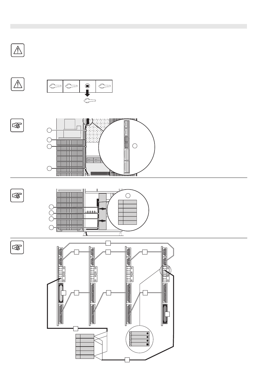
Connecting the modular UPSs with the external bypass
This operation must be carried out by qualified personnel.
The door must be open.
The supplied cables are 10 or 20 m long; The maximum total length must not exceed 180m.
To ensure sufficient isolation of exchange-current, CAN and external-bypass cables, they must be run separately
from the power cables.
On exiting the cabinet, the cables must run along the earthing and connection cables between cabinets.
The handle of the Q3BP switch (in
the OFF position) on all UPS units
must be removed.
UPS cabinet
Key
(1) Connectors
(2) Cable ties
(3) Exchange-current, CAN and
control-wire cables
Bypass cabinet
Key
(1) Connectors
(2) Cable ties
(3) Control-wire cables
Connection with bypass cabinet
Control wires
1. Connect the common, Q3BP ext
and Q5N ext terminals on the terminal
block in the external bypass cabinet to
connector XM4 in UPS4 and XM5 in
UPS1 (cables not supplied).
Exchange current
2. Create a loop between the XM2 and
XM3 connectors in the four UPS units.
All the connectors must be used.
CAN
3. Fit a blue plug on connector XM6 in
UPS1.
4. Interconnect the XM6 and XM7
connectors in the four UPS units.
5. Fit a red plug on connector XM7 in
UPS4.
Q1
Q4S
Q3BP
Q5N
3
2
2
2
1
XM2
XM3
XM4
XM5
XM6
XM7
1
3
2
2
1
1
Q5N ext
Q3BP ext
2
3
4
5
6
COM
2
XM7
XM6
XM3
XM2
XM6
XM3
XM2
1
Q5N ext
Q3BP ext
2
3
4
5
6
COM
1
1
2
2
2
XM7
XM7
XM5
XM5
2
3
4
4
4
XM 4 / XM 5
COM
Q3BP ext
Q5N ext
5
1
4
XM4
Q5N customer
UPS 1
UPS 2
UPS 3
UPS 4
External
bypass
cabinet