External bypass cabinet, 800 kva, Remove the protective covers – APC GALAXY 7000 User Manual
Page 39: Connecting the power cables, Installation
Connecting the power cables >
34020846EN/AD
- Page 39
1. Installation
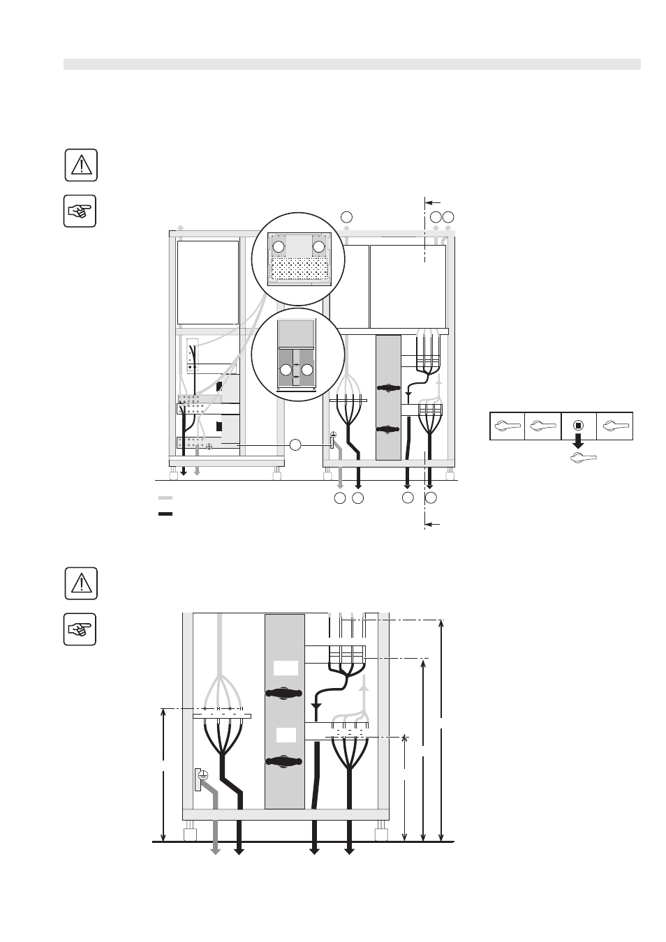
External bypass cabinet
800 kVA
Re m o v e t h e p r o t e c t i v e c o v e r s
This operation must be carried out by qualified personnel.
The door must be opened using a Ronis 405 key.
Key
(1) Front protective covers
(2) Roof protective covers
(3) Earthing bar
(4) To the earth
(5) To the UPSs
(6) To bypass AC line
(7) To the load
1. Remove the protective covers (1)
and/or (2).
The handle of the Q3BP switch (in
the OFF position) on all UPS units
must be removed.
Co n n e c t i n g t h e p o w e r ca b l e s
This operation must be carried out by qualified personnel.
See “Characteristics of the connection terminals”, page 21.
1. Check that switches Q3BP ext and
Q5N ext are in the OFF position as
shown opposite.
2. Connect the protective conductor
(PE or PEN) to the earth bar.
3. Connect the UPS conductors taking
care to respect the order, N*, L1, L2,
L3.
4. Connect the bypass AC conductors
taking care to respect the order, N*,
L1, L2, L3.
5. Connect the load conductors taking
care to respect the order, N*, L1, L2,
L3.
6. Put the protective covers back in
place.
* SLT upstream TNC, downstream TNC, TNS or TT, See “Adapting the cabinet according to the neutral point connection”,
A
6 7
A
5
5
7
6
1
1
2
2
3
4
OFF
OFF
Connection through the top
Connection through the bottom
Right-hand view
Front view
Front
Top view
view
Q1
Q4S
Q3BP
Q5N
N L1 L2 L3
N L1 L2 L3
N L1 L2 L3
533
860
1060
608
Q5N
ext
Q3BP
ext
OFF
OFF
UPSs
Bypass
Load
AC
Earth