Powertrak, Inset a evolution 3000 enclosure, Inset a unit #2 vents – Hired-Hand Evolution Series 3000/3001: Add-On Ventilation Kits User Manual
Page 9: Pcb – 167 power ventilation inset b inset b
Hired-Hand Manufacturing., Inc.
• 1733 Co Rd 68 • Bremen, Alabama 35033 • Phone 256-287-1000 • Fax 256-287-2000
Manual Part No. 4801-5308 rev 09-05
Page 9 of 12
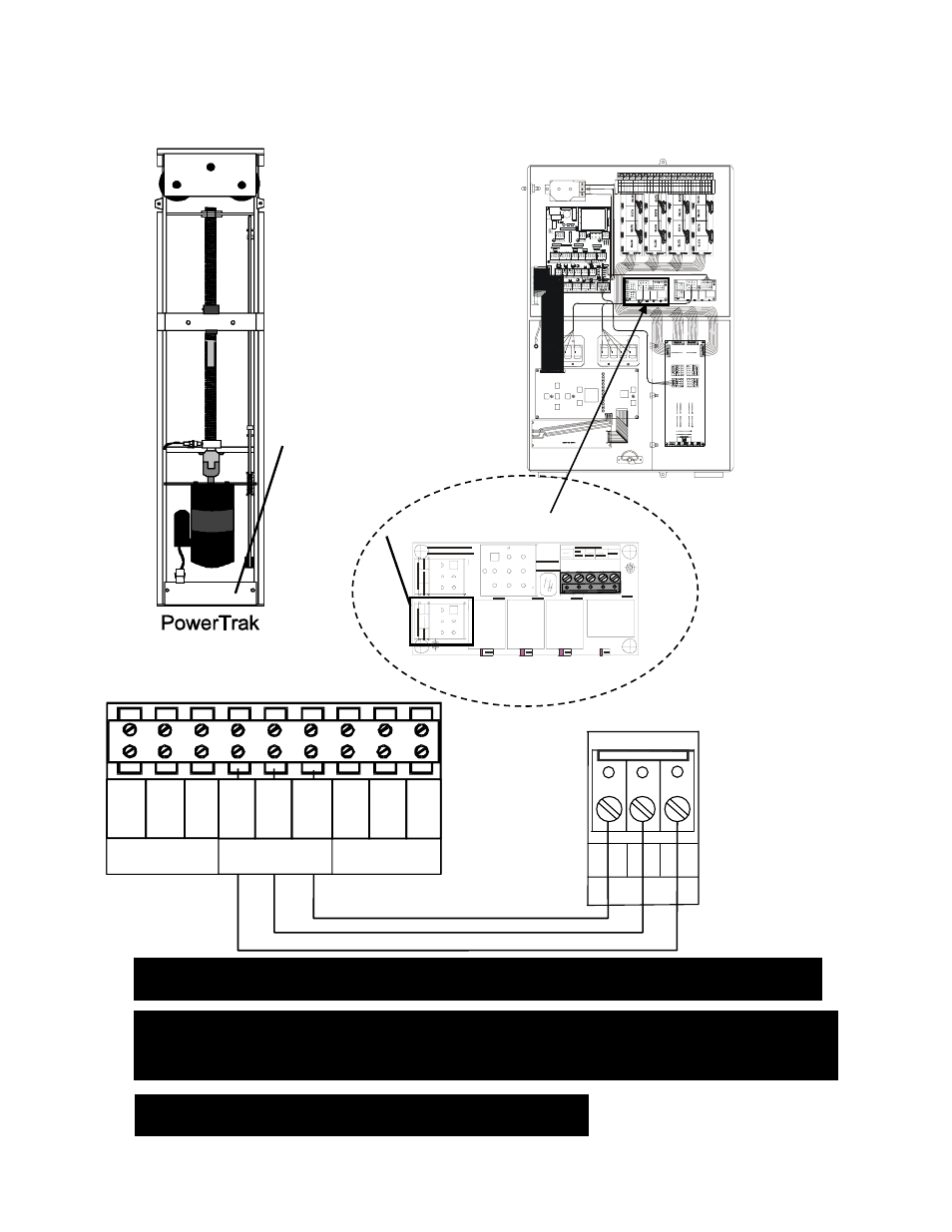
Figure 4: Connecting the PowerTrak to the Evolution 3000
Inset A
Evolution 3000 Enclosure
Hired-Hand
Auxilliary Alarm
Aux Inputs
Sig.
Sig.
Sig.
Sig.
Sig.
Relay Control
Tunnel Aux Inputs Tunnel Aux Inputs
Relay Control
VAR #1
VAR #2
Power Ventilation Module
Variable Module
HHnet Termination
Natural Ventilation Module
DC Power Supply
AC Supply
+12V +5V
L1
L2
Copyright (c) 2000
PCB 169 Rev ‘0’
R
N.C.
IN
Close.
Aux
Close.
Aux
Open
U1
Open
U1
Open
Aux
Open
Aux
Close
Aux
Close
Aux
Open
U2
Open
U2
Close
U2
Close
U2
Close
U1
Close
U1
Com
Com
Com
Com
+12V
+12V
+12V
+12V
+12V
+12V
+12V
N.C.
OUT
nc
Digital Input #1
Sensor 1
Black
Black
Black
Black
Black
Black
Black
Black
Black
White
Shield
White
Shield
White
Shield
White
Shield
White
Shield
White
Shield
White
Shield
White
Shield
White
Shield
Sensor 2
Sensor 3
Sensor 4
Sensor 5
Sensor 6
Sensor 7
Sensor 8
Outside
Local Network
Te
m
p
er
at
ur
e
S
ens
or
s
Te
m
p
era
tu
re
S
ens
or
s
Wind Speed
B.Crider
Analog Input #2
Humidity
Pressure
HHnet
Shield
N.O.
IN
N.O.
OUT
+1 2 V
Rel
ay Con
tro
l
RLY 1
R LY
2
RLY
3
RLY
4
J1
J2
Open
U1
Open
U2
Clos
e
U2
Copy
rig
ht (c
) 20
00
PC
B 1
67 R
ev ‘0
’
Hire
d-H
and
B. C
rid
er
CO
M
U
nit
#1
(V
en
ts)
U
nit
#
2 (
V
en
ts
)
CO
M
Op
en
Op
en
Cl
os
e
C
los
e
D1
D2
D3
D4
+12 V
Rela
y C
ont
rol
RLY 1
RLY 2
RLY
3
R LY
4
J1
J2
Open
U1
Open
U 2
Clos
e
U2
Copy
right
(c)
20
00
PC
B 167
R
ev ‘0’
Hire
d-H
an
d
B. C
rid
er
CO
M
U
nit
#1 (
V
en
ts
)
U
nit
#2
(V
en
ts
)
CO
M
Op
en
Op
en
Cl
os
e
Cl
os
e
D1
D2
D3
D4
Inset A
Unit #2 Vents
Unit #2 Vents
COM
Close
Open
PCB – 167 Power Ventilation
Inset B
Inset B
PowerTrak
AUX
SWITCH
CONTROLLER
AC IN
HOT
NE
UT
.
LOW
E
R
GND
.
HOT
OUT
CL
OSE
IN
O
PEN
IN
COM
U
PPE
R
NOTE: All PowerTrak Units Will Connect The Same.
NOTE: Only 1 PowerTrak can be connected to each PowerTrak outlet. If additional
PowerTraks are needed, the use of relay boxes are necessary to separate the
load.
NOTE: If the curtain is setup to pull curtain up to open, then reverse wires connected
to ‘OPEN’ and ‘CLOSE’.