Hired-Hand Evolution Series 3000/3001: Add-On Ventilation Kits User Manual
Page 3
Hired-Hand Manufacturing., Inc.
• 1733 Co Rd 68 • Bremen, Alabama 35033 • Phone 256-287-1000 • Fax 256-287-2000
Manual Part No. 4801-5308 rev 09-05
Page 3 of 12
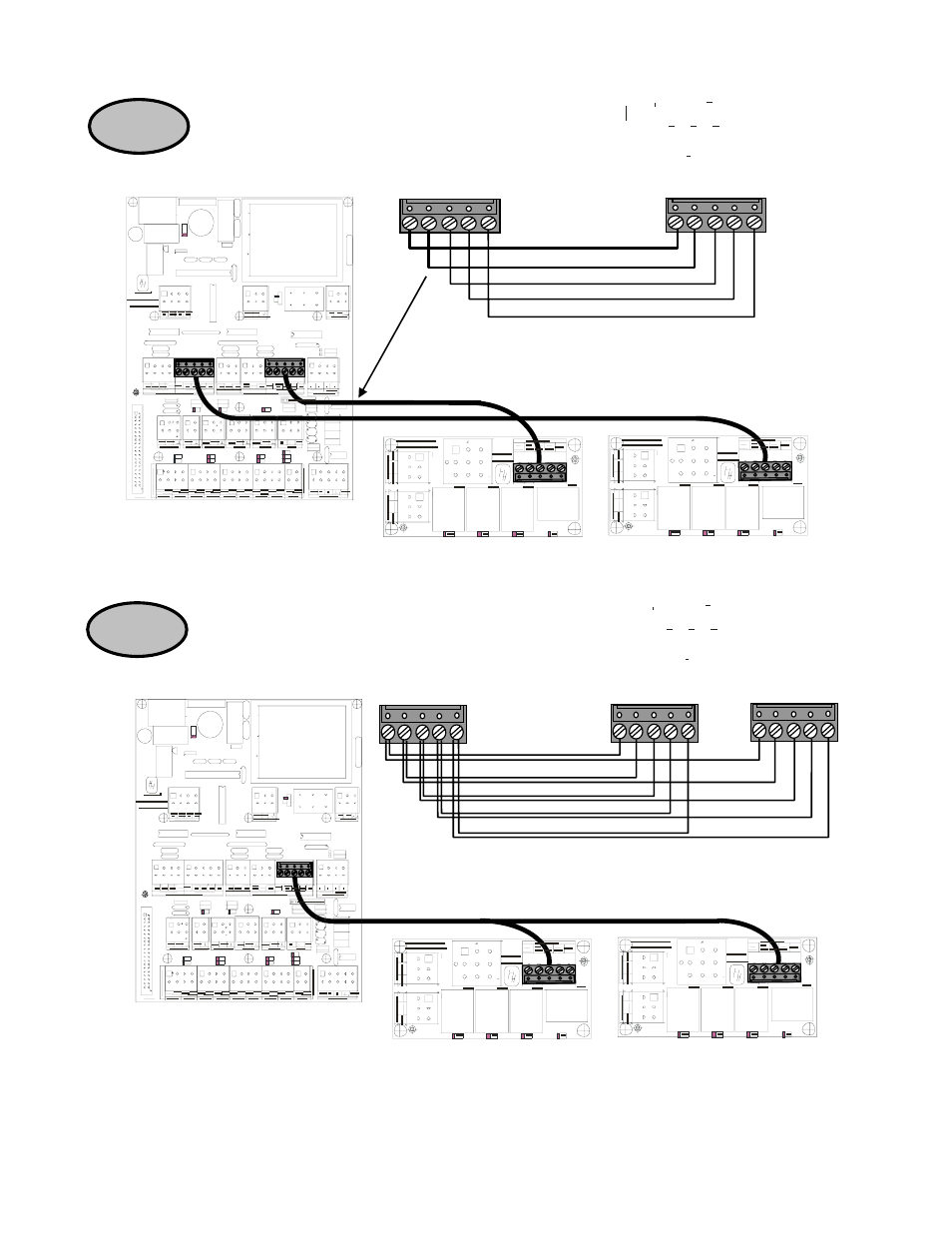
STEP 5
Natural Ventilation
Board (PCB 167)
Input/Output Board (PCB 169)
Power Ventilation
Board (PCB 167)
(or)
STEP 6
(For the Natural or Power Vent Kits) Locate the harness that connects between the Ventilation Board
(PCB 167) and the Input/Output Control Board (PCB 169). See Figure 1 on Page 6 of this document for
the location of the boards. Connect the harnesses from the Ventilation boards (PCB 167) to the Relay
Control on the Input/Output Control Board (PCB 169) as shown below.
(For the Vent Expansion Kit) Locate the harness that connects between the Ventilation Board (PCB 167)
and the Input/Output Control Board (PCB 169). See Figure 1 on Page 6 of this document for the location
of the boards. Connect the harnesses from the Ventilation boards (PCB 167) to the Relay Control on the
Input/Output Control Board (PCB 169) as shown below.
White
Black
Yellow
Red
Orange
Harness between PCB 167 and PCB 169
Natural Ventilation
Board (PCB 167)
Input/Output Board (PCB 169)
Power Ventilation
Board (PCB 167)
(or)
White
Black
Yellow
Red
Orange
Harness between PCB 167 and PCB 169