Hired-Hand Evolution Series 3000/3001: Add-On Ventilation Kits User Manual
Page 5
Hired-Hand Manufacturing., Inc.
• 1733 Co Rd 68 • Bremen, Alabama 35033 • Phone 256-287-1000 • Fax 256-287-2000
Manual Part No. 4801-5308 rev 09-05
Page 5 of 12
STEP 12
STEP 11
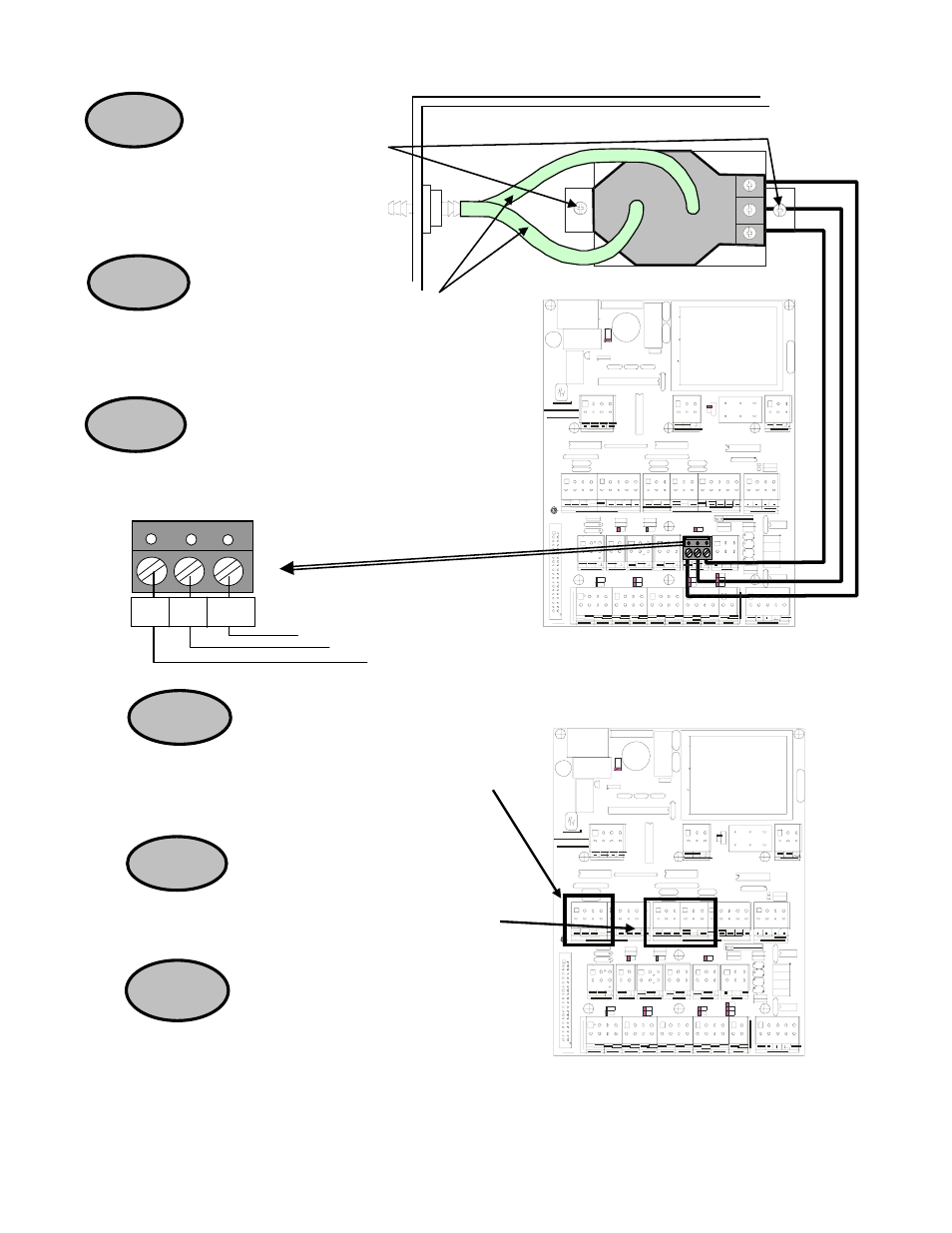
EV Input/Output Board (PCB 169)
STEP 13
(Natural Vent Only) Install the terminal
block for the Natural Ventilation auxiliary switch. See the
wiring diagrams in the Evolution Owners Manual part No.
4801-5307 for the external wiring. See Figure 3.
(Power Vent Only) Install the Terminal
Blocks for the Tunnel and Vent auxiliary switch. See the
wiring diagrams in the Evolution Owners Manual part No.
4801-5307. See Figure 2.
Connect the PowerTraks to the PCB
167 Curtain cards using the supplied terminal blocks
(3006-5082). See the Evolution Owners Manual Part
No. 4801-5307 for wiring. See Figure 4.
(Power Vent Only) Mount the
Static Pressure Transmitter (3591-2252) at
the top left of the Evolution cabinet with
two 10x32x1/2 pan screws (1004-3056)
provided in kit.
STEP 8
STEP 9
(Power Vent Only) Cut two pieces of clear
PVC tubing 5.5” long from the 25 foot roll (6407-0156)
provided with the kit. Install the two pieces of tubing from
the pressure gauge to the fittings in the cabinet side.
NOTE: The HIGH fitting is toward the front.
STEP 10
(Power Vent Only) Install the three-wire harness
(1903-4011) from the EV Input/Output board (PCB 169) to
the Pressure Transducer as shown.
White
Red
Black
12V SIG GND
EV Input/Output Board (PCB 169)
HIGH
LOW
Red
Black
White
-
+
C
O
M
OU
T EXE