Directions – Hired-Hand Evolution Series 3000/3001: Add-On Ventilation Kits User Manual
Page 2
Hired-Hand Manufacturing., Inc.
• 1733 Co Rd 68 • Bremen, Alabama 35033 • Phone 256-287-1000 • Fax 256-287-2000
Manual Part No. 4801-5308 rev 09-05
Page 2 of 12
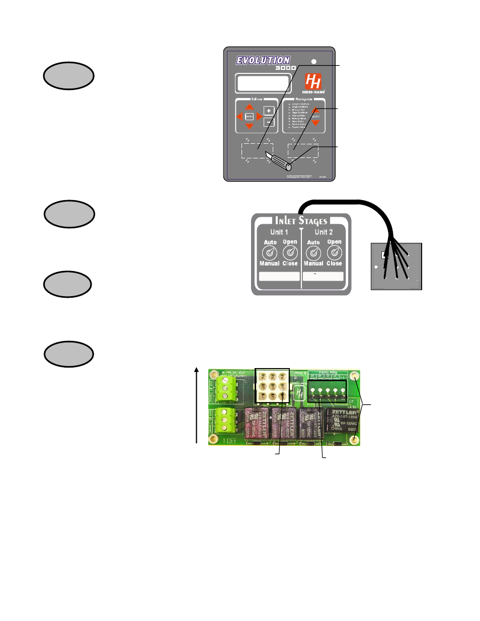
STEP 1
STEP 3
STEP 2
STEP 4
Connector to
Switch panels
Ventilation Board PCB 167
Holes for
Standoff
Top of
enclosure
Harness to I/O
Board
Switch Panels - Natural Ventilation Harness Assembly and
the Power Ventilation Harness Assembly (6407-6017)
Power
Ventilation
Cut-Out
Natural
Ventilation
Cut-Out
Cut out the label around
the switch opening and
the bolt holes with a
small knife.
Directions
First, remove all electrical power
from the Evolution 3000 cabinet and
interconnected equipment
containing voltages that may be fed
back into the Evolution 3000. (Unless otherwise
noted, the following steps are for any of the
Ventilation kits.)
Open the Evolution front panel and locate
the outlined location for the Power or
Natural Ventilation switches as illustrated
on the previous page. Using a small knife,
cut the Evolution label around the opening and around
the four bolt holes.
Locate the Inlet stage switch panels and
harness assemblies shown at the right and
install in the Evolution cut-outs from the
step above. Attach with four 6x32 hx z
nuts (1001-1461) supplied.
Locate the Printed
Circuit Board (PCB
167) in the Add-On
Kit. They are the
same for either the Natural or
Power Ventilation. See Figure 1
on Page 6 of this document for the
location of these boards in the
lower right corner of the Evolution
Cabinet. Press the boards over the
nylon standoffs until a “click is
heard” indicating the boards are
fastened into the standoffs. Insure
that the board is placed so that the
connector to the Ventilator switch
panel is at the TOP. Next,
connect the cable from the Ventilation
Switches to the Ventilation Board.