Hired-Hand Universal Ray Tube Heaters: AG1 Series User Manual
Page 19
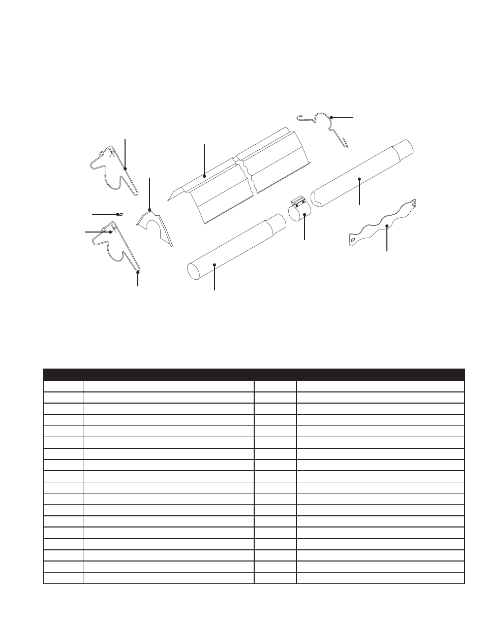
19B
106
105
26F, 26G
21B
20C, 20D*
82
26C
65I
113
19E*
Figure 5.2
•
Tube & Reflector Components
19
5.0
Parts • Heater Components and Parts List
AG1
Series
Co
mb
ust
ion
Tu
be
(s)
Ra
dia
nt E
mit
ter
Tu
be
(s)
Part No. Description
Part No.
Description
TP-200A Burner (50-100 MBH Models)
TP-264B
Differential Pressure Switch, 65 to 75 MBH
TP-201B
Burner (125-150 MBH Models)
TP-264E
Differential Pressure Switch, 100 & 125 MBH
TP-204
Gas Orifice (consult factory)
TP-264D
Differential Pressure Switch, 150 MBH
TP-205
Glo-Bar Holder
TP-301
Center Divider Panel
TP-207
Pressure Switch Mounting Bracket
TP-303A
End Panel, Right
TP-208B Gas Valve Mounting Bracket
TP-304
Burner Control Box Outer Shell
TP-212
1/2” x 3” Pipe Nipple
TP-321
Ignition Plate Gasket
TP-214
Glo-Bar Wiring Harness
TP-330
Divider Grommet
TP-217
Pressure Switch Barb
TP-331
Green Self Tap Ground Screw
TP-218
Differential Switch Vinyl Sensing Tube (exhaust) TP-333
36” Black 120 Volt Plug
TP-219
Differential Vinyl Sensing Tube (burner)
TP-351A
Potted Circuit Circuit Board
TP-221
Glo-Bar Holder Gasket
TP-352A
Circuit Board Wiring Harness for TP-351A
TP-222
Flame Rod
TP-380
16” Burner Tube with Flange
TP-222A Flame Rod Wire
TP-383A
Glo-Bar Ignitor Plate
TP-223
Gas Manifold
TP-826
40VA Transformer
TP-240
Gas Valve Assembly - Natural Gas
TP-828
Amber Operational Indicator Light
TP-241
Gas Valve Assembly - Propane Gas
TP-1402
End Panel, Left