Brocade DCX 8510-8 Backbone Hardware Reference Manual User Manual
Page 71
Messages that may indicate WWN card failure (Continued)
TABLE 9
Type of message
Sample error message
WWN unit removal was detected.
2. Check the LED indicators on the WWN bezel and verify that they reflect the actual status of the
components. The WWN bezel covers the WWN cards and allows its LEDs to shine through. The
LEDs on the WWN bezel provide a consolidated view of the port, CP, and CR blade status.
Refer to the following table for a description of the WWN card LED patterns and the recommended
actions for those patterns.
WWN LED patterns for DCX and DCX 8510-8
TABLE 10
LED location/purpose
Color
Status
Recommended action
Port blade/CP/CR blade
power
Steady green
Power is okay.
No action required.
Port blade/CP/CR blade
status
Steady amber
Card is faulty.
Check card.
No light (LED is off)
Card is okay.
No action required.
NOTE: If a blade slot has a filler panel installed, the corresponding LEDs on the WWN card do not light up.
NOTE: If a status LED on the WWN bezel flashes, the power LED on the WWN bezel also flashes, for
increased visibility.
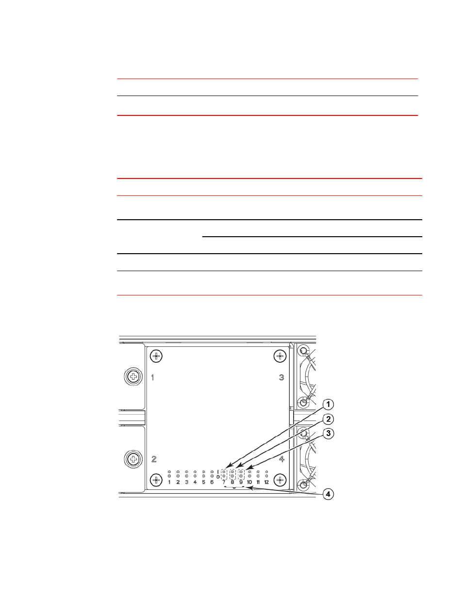
The following figure displays the WWN bezel (logo plate). The WWN cards are under the bezel.
FIGURE 18 WWN bezel (logo plate) with LEDs for DCX and DCX 8510-8
1. CP blade Status (above) and Power (below) LEDs
2. CR blade Status (above) and Power (below) LEDs
Monitoring System Components
Brocade DCX 8510-8 Backbone Hardware Reference Manual
71
53-1002180-07