Brocade 6510 Hardware Reference Manual User Manual
Page 39
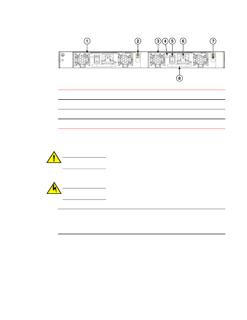
1 Power supply/fan assembly #2
5 On/off switch
2 Airflow label (for nonport side exhaust units only)
6 Power plug receptacle (with plug retainer)
3 Power supply/fan assembly #1
7 Thumbscrew
4 Power supply/fan assembly LED
8 Handle
Switch power supply and fan assemblies on the non-port side
• Disassembling any part of the power supply voids the part warranty and regulatory certifications.
There are no user-serviceable parts inside the power supply and fan assembly.
CAUTION
Changes or modifications made to this device that are not expressly approved by the party
responsible for compliance could void the user's authority to operate the equipment.
• The cooling system relies on pressurized air, do not leave either of the power supply and fan
assembly slots empty longer than two minutes when the Brocade 6510 is operating.
CAUTION
If you do not install a module or a power supply in a slot, you must keep the slot filler panel in
place. If you run the chassis with an uncovered slot, the system will overheat.
NOTE
If a power supply and fan assembly fails, leave the power supply and fan assembly in the Brocade 6510
until it can be replaced. Maintain both power supply and fan assembly in operational condition to
provide redundancy.
The following table describes the power supply and fan assembly status LED colors, behaviors, and
actions required, if any.
Removal and replacement of power supplies and fans
Brocade 6510 Hardware Reference Manual
39
53-1002174-08