Checking the package contents, Model and suffix codes, Gx10/gx20 – Yokogawa Touch Screen GP20 User Manual
Page 7: Gp10/gp20, Models in which i/o modules are preinstalled, I/o modules gx90xa, Gx90xd
5
IM 04L51B01-02EN
Checking the Package Contents
After receiving the product and opening the package,
check the items described below. If the wrong items
have been delivered, if items are missing, or if there is a
problem with the appearance of the items, contact your
nearest Yokogawa dealer.
Check that the product that you received is what you
ordered by referring to the model name and suffix code
given on the name plate on the GX/GP.
NO. (Instrument Number)
When contacting the dealer from which you purchased the
instrument, please give them the instrument number.
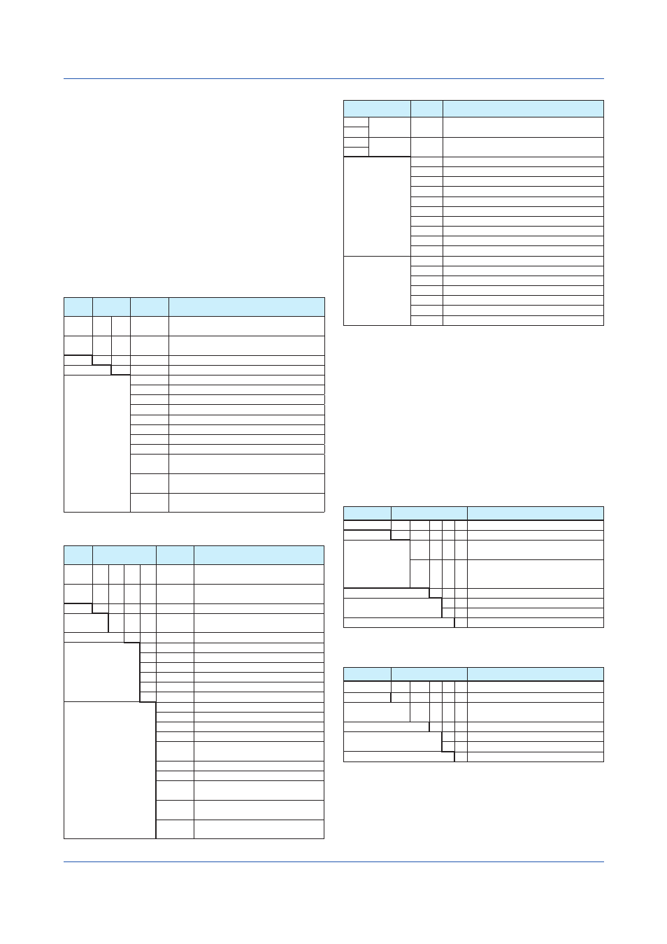
MODEL and SUFFIX Codes
GX10/GX20
Model Suffix
Code
Optional
Code
Description
GX10
Paperless recorder (Panel mount type,
Small display)
GX20
Paperless recorder (Panel mount type,
Large display)
Type
-1
Standard
Language
E
English, degF, DST (summer/winter time)
9
Options
/C2
RS-232
1
/C3
RS-422/485
1
/D5
VGA output
2
/FL
Fail output, 1 point
/MT
Mathematical function (with report function)
/MC
Communication channel function
/P1
24 VDC/AC power supply
4
/UH
USB Interface (host 2 ports)
/UC[ ]0
Analog (universal) input module preinstalled
(clamp terminal)
3
/US[ ]0
Analog (universal) input module preinstalled
(M3 screw terminal)
3
/CR[ ][ ]
Digital output module, digital input module
preinstalled
4
GP10/GP20
Model
Suffix Code
Optional
Code
Description
GP10
Paperless recorder (Portable type,
Small display)
GP20
Paperless recorder (Portable type,
Large display)
Type
-1
Standard
Language
E
English, degF, DST (summer/winter
time)
9
Power supply
1
100 VAC, 240 VAC
Power cord
D
Power cord UL/CSA standard
F
Power cord VDE standard
R
Power cord AS standard
Q
Power cord BS standard
H
Power cord GB standard
N
Power cord NBR standard
Options
/C2
RS-232
1
/C3
RS-422/485
1
/D5
VGA output
2
/FL
Fail output, 1 point
/MT
Mathematical function (with report
function)
/MC
Communication channel function
/UH
USB interface (host 2 ports)
/UC[ ]0
Analog (universal) input module
preinstalled (clamp terminal)
3
/US[ ]0
Analog (universal) input module
preinstalled (M3 screw terminal)
3
/CR[ ][ ]
Digital output module, digital input
module preinstalled
4
Models in Which I/O Modules Are Preinstalled
Model Suffix Code Optional
Code
Description
GX10 -1E/[ ][ ]
Paperless recorder (panel mount type)
GX20
GP10 -1E1[ ]/[ ][ ]
Paperless recorder (portable type)
GP20
Options
(analog Input)
3 10
/UC10
With analog input module, 10ch (Clamp terminal)
/UC20
With analog input module, 20ch (Clamp terminal)
6
/UC30
With analog input module, 30ch (Clamp terminal)
7
/UC40
With analog input module, 40ch (Clamp terminal)
4
/UC50
With analog input module, 50ch (Clamp terminal)
4
/US10
With 10ch analog input module (M3 screw terminal)
/US20
With 20ch analog input module (M3 screw terminal)
6
/US30
With 30ch analog input module (M3 screw terminal)
7
/US40
With 40ch analog input module (M3 screw terminal)
4
/US50
With 50ch analog input module (M3 screw terminal)
4
Options
(digital I/O)
3
/CR01
With digital I/O module (output: 0, input: 16)
7, 8
/CR10
With digital I/O module (output: 6, input: 0)
7
/CR11
With digital I/O module (output: 6, input: 16)
6, 7, 8
/CR20
With digital I/O module (output: 12, input: 0)
5
/CR21
With digital I/O module (output: 12, input: 16)
5, 8
/CR40
With digital I/O module (output: 24, input: 0)
5
/CR41
With digital I/O module (output: 24, input: 16)
5, 8
1
/C2 and /C3 cannot be specified together.
2
/D5 can be specified only for the GX20/GP20.
3
Only one option can be specified.
4
/UC40, /UC50, /US40, and /US50 cannot be specified for the GX10/GP10.
5
/CR20, /CR21, /CR40, and /CR41 cannot be specified for the GX10/GP10.
6
If /UC20 or /US20 is specified for the GX10/GP10, /CR11 cannot be specified.
7
If /UC30 or /US30 is specified for the GX10/GP10, /CR01, /CR10, and /CR11
cannot be specified.
8
A digital input module has M3 screw terminals.
9
The Display language is selectable from English, German, French, Russian,
Korean, Chinese, Japanese. (As of Mar., 2013)
To confirm the current available languages, please visit the following website.
URL: www.yokogawa.com/ns/language/
10 Solid state relay scanner type (Type Suffix Code: -U2).
I/O Modules
GX90XA
Model
Suffix Code
Description
GX90XA
Analog Input Module for GX/GP series
Channels
-10
10 channels
Type
-U2
Universal, Solid state relay scanner
type (3-wire RTD b-terminal common)
-T1
DCV/TC/DI, Electromagnetic relay
scanner type (Isolated between
channels)
-
N
Always N
Terminal type
-3
Screw terminal (M3)
-C
Clamp terminal
1
Area
N General
1
Cannot be specified for the electromagnetic relay scanner type.
GX90XD
Model
Suffix Code
Description
GX90XD
Digital Input Module for GX/GP series
Channels
-16
16 channels
Type
-11
Open collector/Non-voltage, contact
(shared common), Rated 5 VDC
-
N
Always N
Terminal type
-3
Screw terminal (M3)
-C
Clamp terminal
Area
N General