L(+) n(-) – Yokogawa Touch Screen GP20 User Manual
Page 24
22
IM 04L51B01-02EN
Wiring the Power Supply
Use a power supply that meets the following conditions:
Item
Condition (Not /P1) Condition (/P1)
Rated supply voltage 100 to 240 VAC
24 VDC/AC
Allowable power
supply voltage range
90 to 132 VAC,
180 to 264 VAC
21.6 V to 26.4
VDC/AC
Rated power supply
frequency
50/60 Hz
50/60 Hz (for AC)
Permitted power
supply
frequency range
50/60 Hz ± 2%
50/60 Hz ± 2%
(for AC)
Maximum power
consumption
GX10/GP10: 48 VA
GX20/GP20: 90 VA
GX10/GP10: 24 VA
GX20/GP20: 48 VA
100 VAC (/P1: 24 VDC)
Maximum power
consumption
GX10/GP10: 60 VA
GX20/GP20: 110 VA
GX10/GP10: 42 VA
GX20/GP20: 76 VA
240 VAC (/P1: 24 VAC)
Note
Do not use a supply voltage of 132 to 180 VAC, as this
may have adverse effects on the measurement accuracy.
Precautions to Be Taken When Wiring the Power
Supply (GX10/GX20)
Make sure to follow the warnings below when wiring the
power supply. Failure to do so may cause electric shock
or damage to the instrument.
• To prevent electric shock, ensure that
the power supply is turned off.
• To prevent fire, use 600 V PVC in-
sulated wires (AWG20 to AWG16;
JISC3307) or wires or cables with
equivalent or better performance.
• Make sure to earth ground the protec-
tive earth terminal through a ground-
ing resistance of 100 Ω or less before
you turn on the power.
• Use crimp-on lugs (designed for 4
mm screws) with insulation sleeves to
connect both the power cord and the
protective ground.
• To prevent electric shock, be sure to
close the transparent cover for the
power supply wires.
• Provide a power switch (double-pole
type) on the power supply line to
separate the GX/GP from the main
power supply. Use labels to indicate
that this switch is for cutting off the
power supply to the GX/GP and to
indicate ON and OFF.
Switch specifications
Steady-state
current rating
1 A or higher (Not /P1),
3 A or higher (/P1)
Inrush
current rating
60 A or higher (Not /P1),
70 A or higher (/P1)
Must comply with IEC60947-1 and
IEC60947-3.
• Do not add a switch or fuse to the
ground line.
Wiring Procedure (GX10/GX20)
1. Turn off the GX power supply, and then remove the
transparent power supply terminal cover.
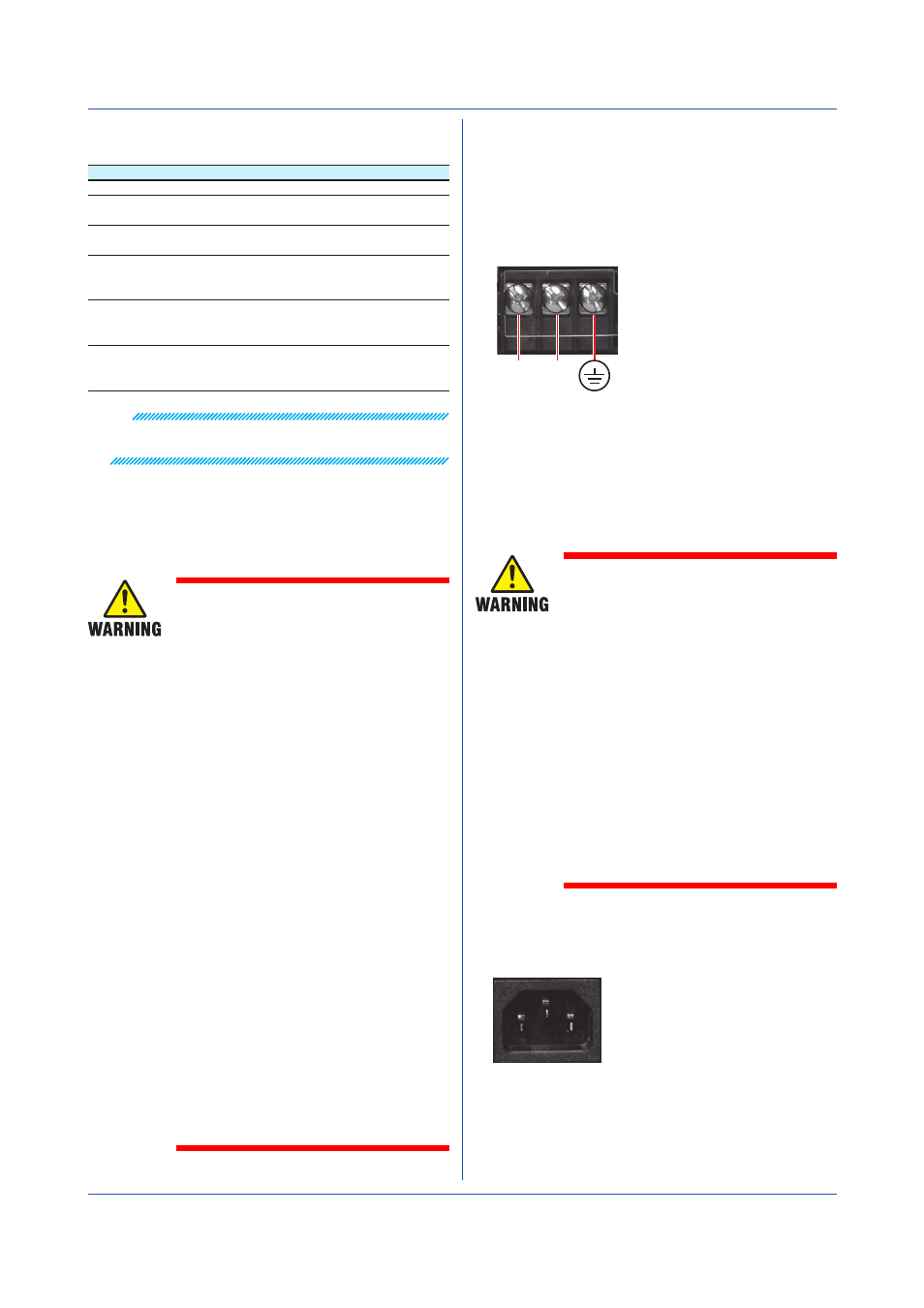
2. Connect the power cord and the protective ground cord
to the power supply terminal. Use ring-tongue crimp-
on lugs (for M4 screws) with insulation sleeves. The
appropriate tightening torque for the screws is 1.4 to
1.5 N•m.
Protective ground
L(+) N(-)
3. Attach the transparent power supply terminal cover,
and fasten it with screws.
Precautions to Be Taken When Connecting the
Power Supply (GP10/GP20)
Make sure to follow the warnings below when connecting
the power supply. Failure to do so may cause electric
shock or damage to the instrument.
• Before connecting the power cord,
ensure that the source voltage
matches the rated supply voltage of
the instrument and that it is within the
maximum rated voltage range of the
provided power cord.
• Connect the power cord after check-
ing that the power switch of the in-
strument is turned OFF.
• To prevent electric shock and fire, be
sure to use a power cord purchased
from Yokogawa Electric Corporation.
• Make sure to connect protective earth
grounding to prevent electric shock.
Insert the power cord into a grounded
three-prong outlet.
• Do not use an extension cord without
protective earth ground. If you do, the
instrument will not be grounded.
Connection Procedure
1. Check that the GP’s power switch is off.
2. Connect the supplied power cord plug to the power
inlet on the rear panel of the GP.
3. Ensure that the source voltage is within the maximum
rated voltage range of the provided power cord. Then,
connect the other end of the cord to the outlet. Use a
grounded three-prong outlet.
Installation and Wiring