Connecting to the vga connector (/d5 option), Connecting to the usb port (/uh option), Connecting to the ethernet port – Yokogawa Touch Screen GP20 User Manual
Page 23
21
IM 04L51B01-02EN
Connecting to the FAIL Output/Status Output (/
FL option)
NC
C
NO
During normal
operation
When a failure
occurs
When power is
turned off
NO C NC
During normal
operation
NO C NC
When the specified
status occurs
NO C NC
NO C NC
NO C NC
NO C NC
When power is
turned off
FAIL
output
Status
output
Recommended torque for tightening the screws: 0.5N•m
Connecting to the Serial Communication
Interface (/C2 option)
1
2
3
4
5
9
8
7
6
DSUB 9-pin male
2 RD (Received Data)
3 SD (Send Data)
5 SG (Signal Ground)
7 RS (Request to Send)
8 CS (Clear to Send)
Pins 1, 4, 6, and 9 are not used.
Connecting to the RS-422/485 Connector (/C3 option)
Two-wire system
Four-wire system
FG SG SDB+ SDA– RDB+ RDA–
FG SG SDB+ SDA– RDB+ RDA–
Electric potential
of the shield
Shield
FG SDB+
SG SDA−
Electric potential
of the shield
Shield
FG SDB+
SG SDA−
RDB+
RDA−
FG (Frame Ground)
Case ground of the GX/GP
SG (Signal Ground)
Signal ground
SDB+ (Send Data B+)
Send data B (+)
SDA− (Send Data A−)
Send data A (–)
RDB+ (Received Data B+) Receive data B (+)
RDA− (Received Data A−) Receive data A (–)
Recommended torque for tightening the screws: 0.2N•m
Connecting to the VGA Connector (/D5 option)
1
5
6
10
15
11
Pin No. Signal Name Specifications
1
Red
0.7 Vp-p
2
Green
0.7 Vp-p
3
Blue
0.7 Vp-p
4
―
5
―
6
GND
7
GND
8
GND
9
―
10
GND
11
―
12
―
13
Horizontal
sync signal
Approx. 39.1 kHz, TTL negative logic
14
Vertical sync
signal
Approx. 60 Hz, TTL negative logic
15
Installation and Wiring
• Only connect the GX/GP to a monitor
after turning both the GX/GP and the
monitor off.
• Do not short the VIDEO OUT con-
nector or apply external voltage to it.
Doing so may damage the GX/GP.
Connecting to a Monitor
1. Turn off the GX/GP and the monitor.
2. Connect the GX/GP and the monitor using an RGB
cable.
3. Turn on the GX/GP and the monitor. The GX/GP
screen appears on the monitor.
Note
• When the GX/GP is turned on, the VIDEO OUT
connector constantly transmits VGA signals.
• The monitor display may flicker if you place the GX/
GP or some other device close to it.
• Depending on the type of monitor, parts of the GX/GP
display may be cut off.
Connecting to the USB Port (/UH option)
A USB2.0 compliant port (see “Component Names”)
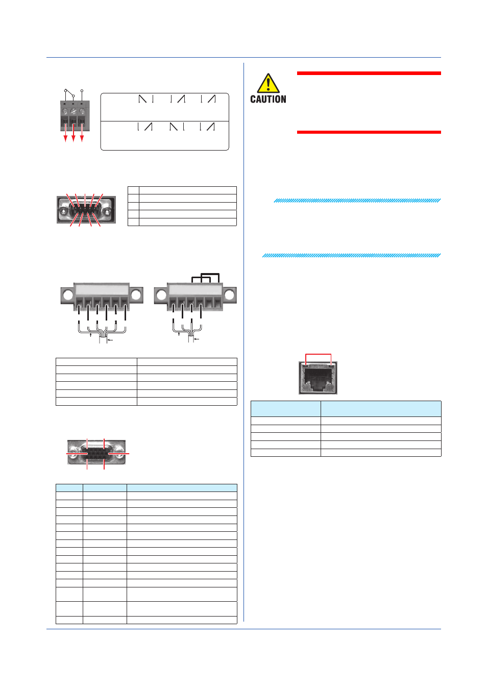
Connecting to the Ethernet Port
Checking the Connection and Communication Status
You can use the indicators that are located above the
Ethernet port to check the connection status of the
Ethernet interface.
Indicators
Yellow green
Orange
Indicator
Connection Status of the Ethernet
Interface
Lit (yellow-green)
The Ethernet link is established.
Off (yellow-green)
The Ethernet link is not established.
Blinking (yellow-green) Receiving data
Lit (orange)
Connected at 100 Mbps
Off (orange)
Connected at 10 Mbps