11 signal characterizer, 12 alarm, Signal characterizer -22 – Yokogawa EJX115A User Manual
Page 35: Alarm -22
<3. Parameter Setting>
3-22
IM 01C25T01-06EN
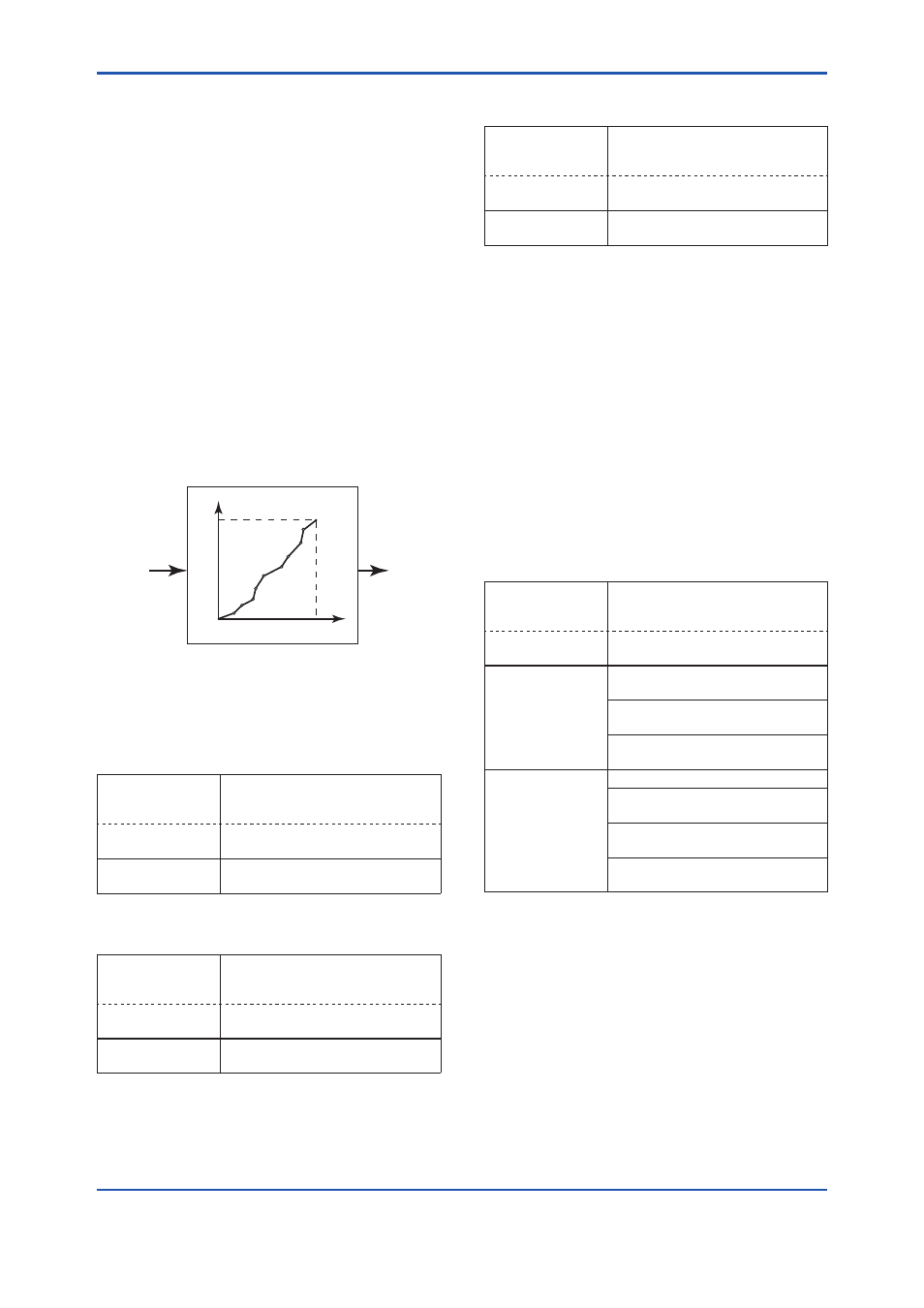
3.3.11 Signal Characterizer
This function is used to compensate the output
for non-linear applications. The characterized
values are applied to the 4-20 mA output. For
the measured pressure, a maximum of nine
coordinates can be specified between 0-100%.
Perform the coordinate settings while the
S.C. at
S.C. menu parameter is “Disabled”.
To apply the settings to the output, set the
S.C.
parameter to “Enabled”.
Note that the transmitter rejects the activation of the
function by AL. 60 with the following transmitter’s
status:
• When the specified coordinates of x and y are
not incremental as the input increases.
• When the output mode of the output signal is
set as “Sq root”; at the same time, the low cut
mode is set to “Linear”.
F0308.ai
Y
X
100%
0%
100%
INPUT
OUTPUT
Input pressure in %
Characterized value
Follow the steps below to perform the signal
characterizer.
<1> Set the desired number of coordinates on the
line graph
• Procedure to call up the display
DD and DTM
(excluding EJX_
HART 5[1.2])
[Root Menu] → Detailed setup →
Signal condition → S.C. menu →
EJX_HART 5[1.2]
DTM
Configuration → Signal
Characterizer Menu →
→ Num of points
Set the number between 0 and 9
<2> Set the coordinates
• Procedure to call up the display
DD and DTM
(excluding EJX_
HART 5[1.2])
[Root Menu] → Detailed setup →
Signal condition → S.C. menu →
EJX_HART 5[1.2]
DTM
Configuration → Signal
Characterizer Menu →
→ Point setting
Set the coordinates (X-axis,
Y-axis)
<3> Apply the settings
• Procedure to call up the display
DD and DTM
(excluding EJX_
HART 5[1.2])
[Root Menu] → Detailed setup →
Signal condition → S.C. menu →
EJX_HART 5[1.2]
DTM
Configuration → Signal
Characterizer Menu →
→ S.C.
Select “Enabled” or “Disabled”
3.3.12 Alarm
The function is used to display the alarm codes
when the input pressure exceeds the specified
value within the calibration range. The same is
available for the input static pressure and the
capsule temperature on the pressure sensor.
Refer to table 4.5 Alarm Message Summary for the
specific alarm code to be generated.
(1) Alarm Setting
Select the process variable at
Process Alert which
the alarm is set, then set the alert mode for that
value.
• Procedure to call up the display
DD and DTM
(excluding EJX_
HART 5[1.2])
[Root Menu] → Detailed setup
→ Output condition → Process
Alerts →
EJX_HART 5[1.2]
DTM
Configuration → Process Alerts →
Selection of the
process variable
for alarm
→ Pres Alert (DTM only) →
Pres Alert mode: Pressure
→ SP Alert (DTM only) →
SP Alert mode: Static pressure
→ Temp Alert (DTM only) → Temp
Alert mode: Capsule temperature
Selection of alert
mode
Off: Disable the alert function
Hi. Al Detect: High side alert
detection
Lo. Al Detect: Low side alert
detection
Hi/Lo. Al Detect: High and Low
side alert detection