3 range change, 4 output mode, 5 damping time constant setup – Yokogawa EJX115A User Manual
Page 26: Range change -13, Output mode -13, Damping time constant setup -13
<3. Parameter Setting>
3-13
IM 01C25T01-06EN
3.2.3 Range Change
The range values are factory-set as specified by
the customer. To change the range, follow the steps
below.
(1) Keypad input — LRV and URV
The measurement span is determined by the upper
and lower range values. In this method, the upper
and lower range values can be set independently,
and the span changes according to the range limit
values sent to the transmitter.
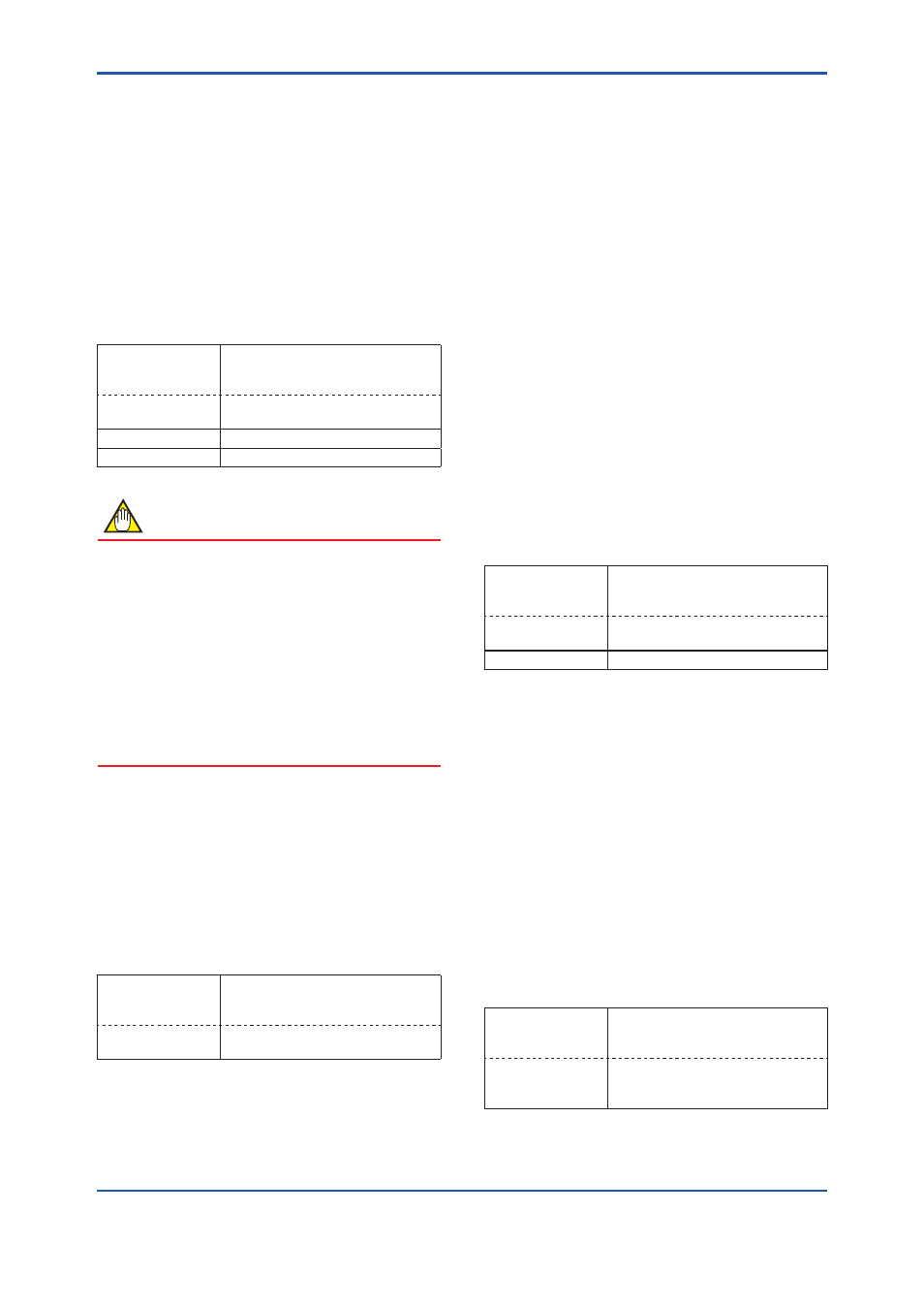
• Procedure to call up the display
DD and DTM
(excluding EJX_
HART 5[1.2])
[Root Menu] → Basic setup →
Re-range → Keypad input
EJX_HART 5[1.2]
DTM
Easy Setup → or Configuration →
Analog Output →
→ LRV
Lower range value
→ URV
Upper range value
NOTE
The calibration range can be set as LRV > URV
under the following conditions, reversing the 4
to 20 mA output signal. When using the integral
indicator, change the user set scale values
accordingly.
Conditions:
LSL ≤ LRV ≤ USL
LSL ≤ URV ≤ USL
|URV – LRV| ≥ Min Span
LSL: Lower sensor limit of range setting
USL: Upper sensor limit of range setting
(2) Apply values — changing the ranges while
applying an actual Input
This feature allows the lower and upper range
values to be setup automatically with the actual
input applied. If the upper and lower range values
are set, URV and LRV are changed at the same
time.
• Procedure to call up the display
DD and DTM
(excluding EJX_
HART 5[1.2])
[Root Menu] → Basic setup →
Re-range → Apply values →
EJX_HART 5[1.2]
DTM
Configuration → Analog Output →
Apply values →
The measurement span is determined by the upper
and lower range values. Changing the lower range
value causes the upper range value to change
automatically, keeping the span constant. If a
change in the lower range value causes the upper
range value to exceed the measuring limit of the
transmitter, an error message appears and the
transmitter holds the output signal right before the
error occurred. Enter the correct values within the
range of the sensor limits.
Note that changing the upper range value does
not cause the lower range value to change. Thus,
changing the upper range value also changes the
span.
3.2.4 Output Mode
The mode setting for the output signal and the
integral indicator can be performed independently.
The output mode for the output signal is set as
specified in the order when the instrument is
shipped. Follow the procedure below to change the
mode.
• Procedure to call up the display
DD and DTM
(excluding EJX_
HART 5[1.2])
[Root Menu] → Basic setup →
EJX_HART 5[1.2]
DTM
Easy Setup → or Configuration →
Analog Output →
→ Xfer fnctn
Select “Linear” or “Sq root”
3.2.5 Damping Time Constant Setup
The damping time constant is set as specified in
the order when the instrument is shipped. Follow
the procedure below to change the damping
time constant. The damping time constant for the
amplifier assembly can be set here. The damping
time constant for the entire transmitter is the sum
of the values for the amplifier assembly and the
capsule assembly.
Any number from 0.00 to 100.00 can be set for the
damping time constant. Note that setting the quick
response parameter ON enables you to set the time
constant between 0.00 and 0.49 seconds.
• Procedure to call up the
Pres Damp display
DD and DTM
(excluding EJX_
HART 5[1.2])
[Root Menu] → Basic setup →
Pres Damp
EJX_HART 5[1.2]
DTM
Easy Setup → Pres Damp or
Configuration → Analog Output →
Pres Damp