Output 2 solid-state relay, Output 2 switched dc, Output 2 open collector – Watlow Series PD Ethernet Enabled Temperature and Process Controller User Manual
Page 17: Figure 15a, Figure 15b, Figure 15c
W a t l o w S e r i e s P D
■
15
■
C h a p t e r 2 I n s t a l l a n d W i r e
ç
Warning:
Use National Electric (NEC) or
other country-specific standard
wiring and safety practices when
wiring and connecting this con-
troller to a power source and to
electrical sensors or peripheral
devices. Failure to do so may re-
sult in damage to equipment and
property, and/or injury or loss of
life.
Quencharc Note:
Switching pilot duty loads (relay
coils, solenoids, etc.) with the
mechanical relay or solid-state
relay output options requires use
of an R.C. suppressor.
Watlow carries the R.C. suppres-
sor Quencharc brand name,
which is a trademark of ITW
Paktron. Watlow Part No. 0804-
0147-0000.
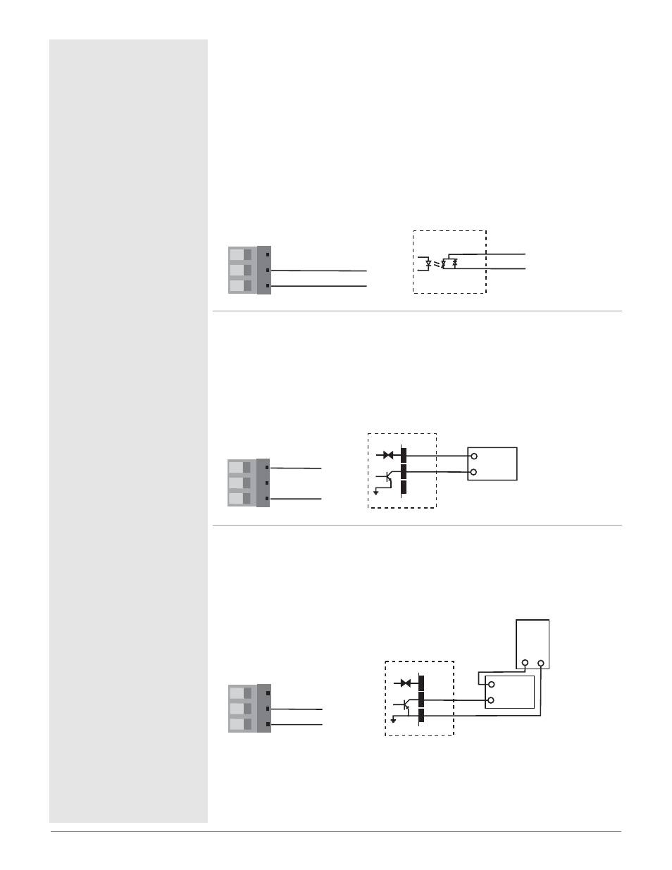
Figure 15a —
Output 2 Solid-state Relay
PD_ _ - _ K _ _ - _ _ _ _
• Form A contact
• 0.5 A, resistive
• 20 VA pilot duty, 120/240VÅ (ac), inductive
• 24 to 240VÅ (ac)
• See Quencharc note
• Minimum load current 10mA
• Maximum leakage current 100µA
• Not for use with direct current (dc)
• Output does not supply power
Figure 15b —
Output 2 Switched DC
PD_ _ - _ C _ _ - _ _ _ _
• Maximum supply current 30 mAÎ (dc)
• Supply voltage 24VÎ (dc)
• Not recommended for switching mechanical relays
• Output supplies power
Figure 15c —
Output 2 Open Collector
PD_ _ - _ C _ _ - _ _ _ _
• Maximum current sink 250 mAÎ (dc)
• Maximum supply voltage 42VÎ (dc)
• Output does not supply power
Internal Circuitry
dc-
COM.
dc+
42VÎ (dc) maximum
Open Collector
16
18
17
Load
-
+
Power
Supply
-
+
Class 2 power source
required for agency
compliance.
16 17 18
18 dc -
16 dc +
17 com
Internal Circuitry
dc-
dc+
24VÎ (dc)
Load
Switched DC
-
+
16
18
16 17 18
18 dc -
16 dc +
17 com
Internal Circuitry
COM.
N.O.
Solid-state Relay
17
18
Solid-state Switch
16 17 18
18 normally open
17 com