One digital and one ct input, Digital input 1, Voltage input – Watlow Series PD Ethernet Enabled Temperature and Process Controller User Manual
Page 13: Contact closure
W a t l o w S e r i e s P D
■
11
■
C h a p t e r 2 I n s t a l l a n d W i r e
ç
Warning:
Use National Electric (NEC) or
other country-specific standard
wiring and safety practices when
wiring and connecting this con-
troller to a power source and to
electrical sensors or peripheral
devices. Failure to do so may re-
sult in damage to equipment and
property, and/or injury or loss of
life.
Note: Current transformer (CT)
must be purchased separately.
Note: A current transformer input
cannot be associated with a
process output on Output 1 or 3.
Note: Install a 1k
Ω
pull-down
resistor for each digital in-
put using voltage inputs.
Note: Install a 10k
Ω
pull-up re-
sistor for each digital input
using contact closure in-
puts.
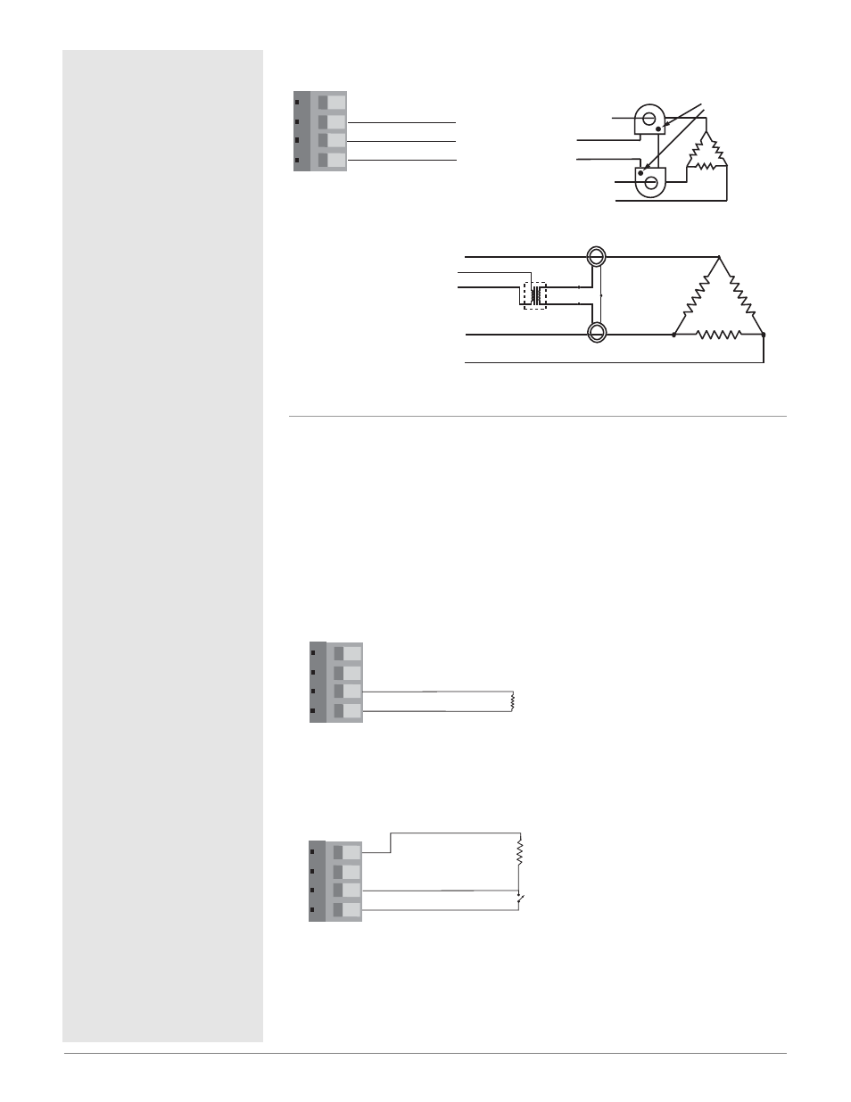
Figure 11a —
Three Phase using Two Current Transformers
One Digital Input and One Current Transformer Input
PD_ 2-_ _ _ _-_ _ _
Digital Input 1
• Input impedance 10k
Ω
, dc only
Figure 11b —
Voltage input
0-1VÎ (dc) Event Input Low State
2-36VÎ (dc) Event Input High State
Figure 11c —
Contact closure
0-2k
Ω
Event Input Low State
> 7k
Ω
Event Input High State
1
2 3 4
4
1
+5V‡ (dc)
2
3
Digital Common
Digital Input 1
10k
Ω
Contact Closure
(add a 10k
Ω
pull
up resistor for each
active input)
1
2 3 4
1
2
Digital Common
Digital Input 1 +
-
1k
Ω
Add a 1k
Ω
pull
down resistor for
each active input
1
2 3 4
Bk
Red
Red
Wh
Bk
Bk
Wh
Bk
16-0176
Transformer
CT
CT
L1
L3
L2
5A
20mA
3-phase current sensing up to 300 amp
To CT Input 1 or 2
To CT Common
1
2
3
CT Common
CT Input 1
CT Input 2
L3
L1
L2
Phase
dot
To CT Input 1 or 2
To CT Common