Dual digital inputs, Input 1, 0 to 20 ma process input, Input 2, 0 to 20 ma process input – Watlow Series PD Ethernet Enabled Temperature and Process Controller User Manual
Page 11: Voltage input, Contact closure
W a t l o w S e r i e s P D
■
9
■
C h a p t e r 2 I n s t a l l a n d W i r e
Ó
Warning:
Use National Electric (NEC) or
other country-specific standard
wiring and safety practices when
wiring and connecting this con-
troller to a power source and to
electrical sensors or peripheral
devices. Failure to do so may re-
sult in damage to equipment and
property, and/or injury or loss of
life.
ç
WARNING: Process input may
not have sensor break protec-
tion. Outputs can remain full on.
Note: Install a 1k
Ω
pull-down
resistor for each digital in-
put using voltage inputs.
Note: Install a 10k
Ω
pull-up re-
sistor for each digital input
using contact closure in-
puts.
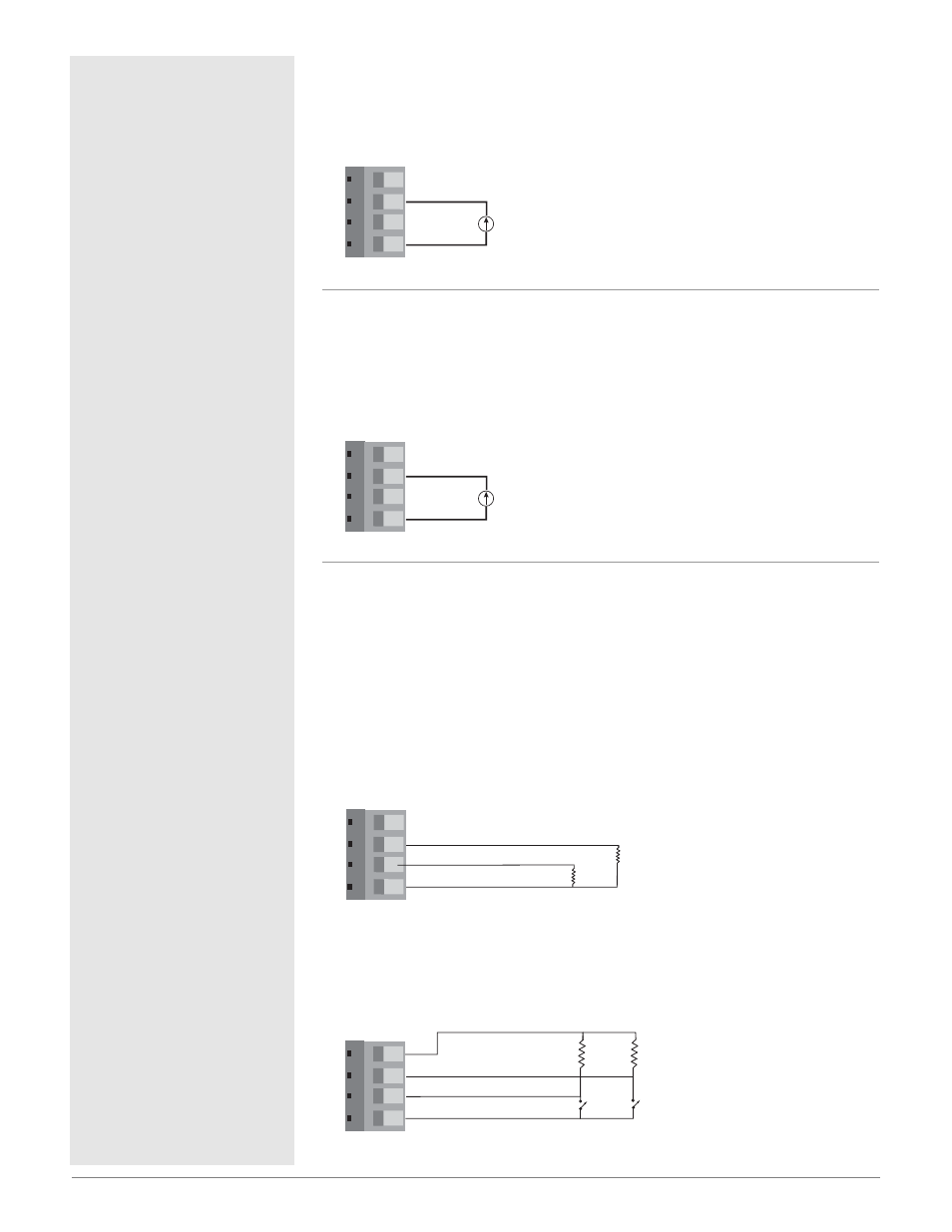
Figure 9a —
Input 1, 0 to 20 mA Process Input
(all model numbers)
• Input impedance 100
Ω
, dc only
• Controller does not supply power for the current loop
Figure 9b —
Input 2, 0 to 20 mA Process Input
PDD _-_ _ _ _-_ _ _
• Input impedance 100
Ω
, dc only
• Controller does not supply power for the current loop
• Input 2 isolated from Input 1
Dual Digital Inputs
PD_ 1-_ _ _ _-_ _ _
• Input impedance 10k
Ω
, dc only
• Input 2 isolated from Input 1
Figure 9c —
Voltage input
0-1VÎ (dc) Event Input Low State
2-36VÎ (dc) Event Input High State
Figure 9d —
Contact closure
0-2k
Ω
Event Input Low State
> 7k
Ω
Event Input High State
1
2 3 4
4
1
+5V‡ (dc)
2
3
Digital Common
Digital Input 1
Digital Input 2
10k
Ω
10k
Ω
Add a 10k
Ω
pull
up resistor for each
active input
1
2 3 4
1
2
3
Digital Common
Digital Input 1 +
Digital Input 2 +
-
1k
Ω
1k
Ω
Add a 1k
Ω
pull
down resistor for
each active input
5
6 7 8
7
5
+
-
9
10 11 12
11
9
+
-