Spade terminal model, Screw terminal models spade terminal model, Tactile key, screw terminal model – Watlow Series TM User Manual
Page 6
Wa t l o w S e r i e s C
• 4 •
C h a p t e r 2 I n s t a l l a t i o n
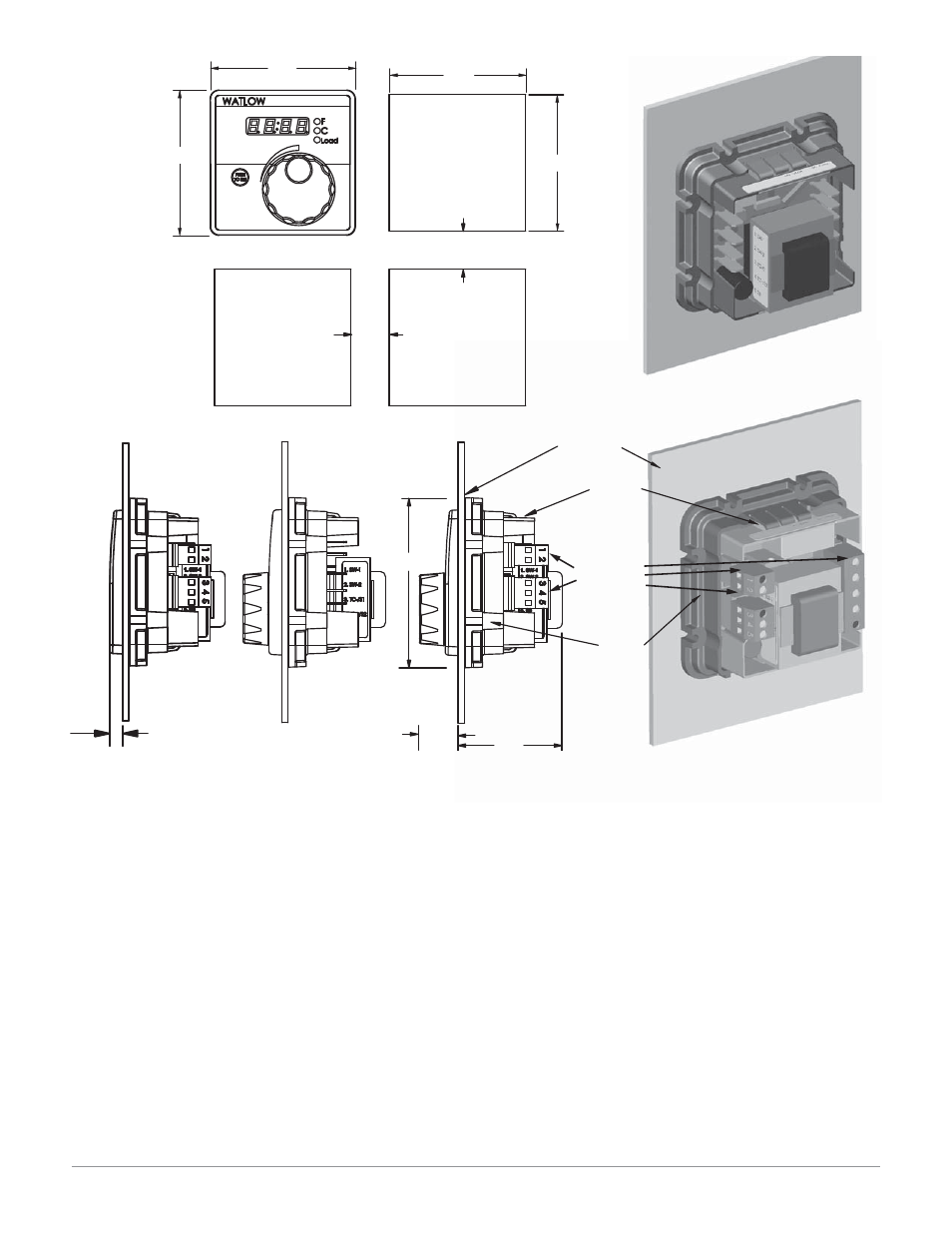
Figure 4
Installing the Square 1/8 DIN Panel Mount
Controller
1. Make the panel cutout using the mounting dimen-
sions above.
2. Remove mounting bracket from the back of the con-
troller.
3. If your controller has a gasket, check to see that the
gasket is not twisted, and is seated within the case
bezel flush with the panel. Place the case in the
cutout. Make sure the gasket is between the panel
cutout and the case bezel.
4. While pressing the front of the case firmly against
the panel, slide the mounting collar over the back of
the control. The tabs on the collar must line up with
the mounting ridges on the case for secure instal-
lation. See Figure 4. Slide the collar firmly against
the back of the panel, getting it as tight as possible.
To ensure a tight seal, use your thumb to lock the
tabs into place while pressing the case from side to
side. Don’t be afraid to apply enough pressure to in-
stall the controller. The tabs on each side of the col-
lar have teeth that latch into the ridges. Each tooth
is staggered at a different height, so only one of the
tabs on each side are ever locked into the ridges
at a time. Confirm that the tabs on one side of the
collar correspond with those on the opposite side.
Make sure the two corresponding tabs are the only
ones locked in the ridges at the same time. If the
corresponding tabs are not supporting the case at
the same time, you will not have a NEMA 4X seal.
5. Insert the control chassis into its case and press the
bezel to seat it. Make sure the inside gasket is also
seated properly and not twisted. The hardware in-
stallation is complete. Proceed to the wiring section.
Terminal Blocks Locations
on Screw Terminal Models
Spade Terminal Model
Contact your local Greenlee supplier for the appropriate
punch kit and cutout tool for rapid mounting.
Screw Terminal Models
Spade Terminal Model
72.4 mm
(2.85 in)
72.4 mm
(2.85 in)
68.0 mm
(2.68 in)
68.0 mm
(2.68 in)
19.1 mm
(0.75 in)
minimum
19.1 mm
(0.75 in)
minimum
Panel Cutout
Panel Thickness
1.52 to 3.18 mm
(0.060 to 0.125 in)
84.5 mm square
(3.33 in)
19.2 mm
(0.76 in)
51.7 mm
(2.04 in)
Customer Front Panel
Part Number Label
Mounting Bracket
6.4 mm
(0.25 in)
Tactile Key,
Screw Terminal Model