Installation, Installing the open board controller, Installing the potted controller – Watlow Series TM User Manual
Page 4: Spade terminal model, Screw terminal model
Wa t l o w S e r i e s C
• 2 •
C h a p t e r 2 I n s t a l l a t i o n
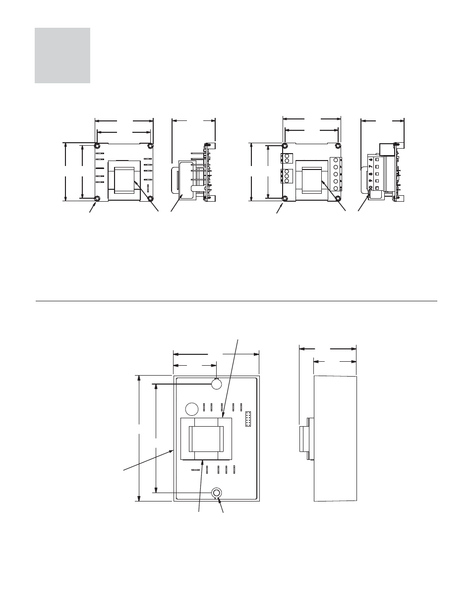
Installing the Open Board Controller
Spade Terminal Model
61.7 mm
2.43 in
55.9 mm
2.20 in
Use M2.5 (#4) mounting
hardware, not included
56.3 mm
2.22 in
61.7 mm
2.43 in
45.07 mm
1.775 in
Terminal Designation Sticker
Terminal Designation Sticker
61.7 mm
2.43 in
55.9 mm
2.20 in
56.3 mm
2.22 in
61.7 mm
2.43 in
Use M2.5 (#4) mounting
hardware, not included
45.07 mm
1.775 in
.6
.7
.8
.9
.10
SWDC+
N.O.
SWDC-
COM
N.C.
L2
L1
Screw Terminal Model
Figure 2a
1. Locate and drill four 3.2 mm (0.125 in) holes in the desired panel location. See Figure 2a for hole locations.
2. Mount the controller using four M2.5
(#4) screws.
Installing the Potted Controller
70.1 mm
2.76 in
35.1 mm
1.38 in
88.9 mm
3.50 in
Terminal Designation Sticker
Use [3.5M] #6 hardware,
not included
35.1 mm
1.38 in
46.6 mm
1.84 in
Terminal Designation Sticker
102.9 mm
4.05 in
Terminal Designation Sticker
Figure 2b
1. Drill two 5 mm (0.187 in) diameter holes in the desired panel location. See Figure 2b for hole locations.
2. Mount the controller using two M3.5
(#6) screws.
2
Installation