Location considerations, Control panel design guidelines – Maple Systems HMC7000 Series User Manual
Page 7
HMC7000 Series Installation Guide
Maple Systems Inc., 808 134th Street SW, Suite 120, Everett, WA 98204-7333 • www.maplesystems.com
.
1010-1042
Page 5 of 22
Rev. 02, 09/25/2013
Location Considerations
Care should be taken when locating equipment behind the
HMC7000
to ensure that AC power wiring, PLC output
modules, contactors, starters, relay and any other source of electrical interference are located away from the
HMC7000
.
Particular care should be taken to locate variable speed drives and switching power supplies away from the HMC.
Control Panel Design Guidelines
Panel Preparation
A metal panel or mounting surface is required. The minimum thickness should be 15 gauge (0.059 in/3.3 mm) if cold-
rolled steel or hardened steel is used. Use 10 gauge (0.101 in/2.6 mm) if aluminum alloy (6061-T6 preferred) is used.
Thinner panels or surfaces may bow between the mounting clamps and not form a seal with the gasket. Make sure all
supplied mounting clamps are used and that the panel does not flex or bow more than 0.010 in. to ensure a proper seal.
Maximum thickness should be no more than 0.26” or 6.5mm.
The HMC should be mounted into a panel with a depth of at least 4 in. (105 mm). Allow a clearance of at least 1 in. (25
mm) on each side for mounting hardware. Consider proper clearance for cable connections when mounting.
NOTE: Cutout dimensions for each particular HMC model are readily available for download from the Support Center-
Dimensional Drawings section of the Maple Systems website
Warning: The HMC requires a stiff, flat, smooth mounting surface free of blemishes, scratches, or pits in order that the
gasket seal properly to NEMA 4. If the panel or mounting surface is not uniform, thick, flat, stiff, or smooth enough,
then a sealant such as silicone may be required.
NOTE: Clean and deburr the panel cutout before the HMC is installed
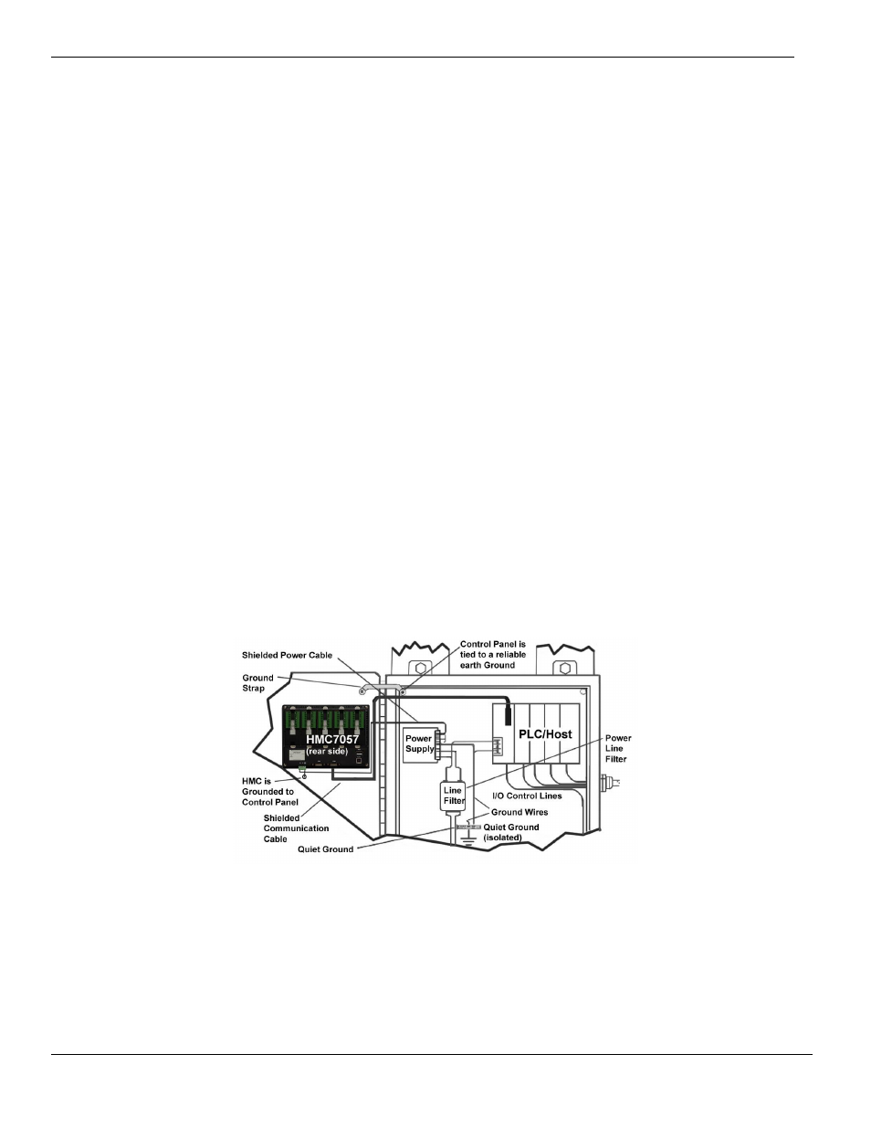
Pay careful attention to the placement of system components and associated cable routing. These items can significantly
enhance the performance and integrity of your control application.
Figure 1: Typical Panel Layout