Maple Systems HMC7000 Series User Manual
Page 10
HMC7000 Series Installation Guide
Phone: 425/745-3229 • Fax: 425/745-3429 • Email: [email protected] • www.maplesystems.com
1010-1042
Page 8 of 22
Rev. 02, 09/25/2013
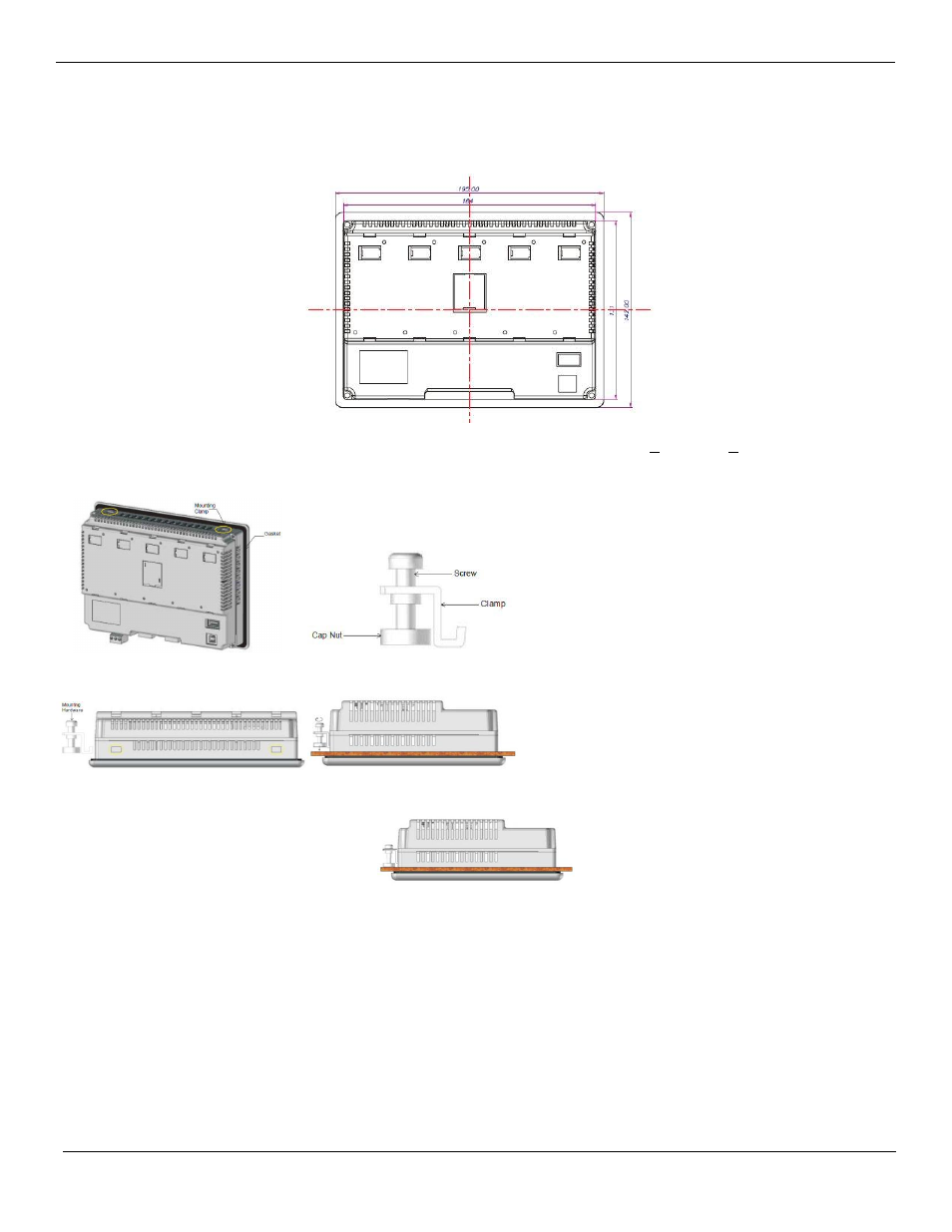
Panel Cutout and Mounting for the HMC7057 models:
Below is the panel cutout (7.24”x5.16” [184x131 mm]) and mounting dimensions for all 5.7” LCD models:
Note: the maximum panel thickness should be no more than 0.26” [6.5mm] (tolerance + 0.0004” [+0.01mm])
►Procedure to mount the unit:
Figure 1
Figure 2
Figure 3
Figure 4
Figure 5: Make a cutout in the panel to the required size.
Place the unit into the panel. The sealing gasket is placed directly behind the HMC bezel. (Note: use a sealing
adhesive in installations in which the panel surface is rough or uneven).
On each HMC, there are four mounting slots. Four mounting clamps (with clamp, bolt, and cap nut) are included
with each HMC. Insert each clamp into the mounting slots. Hold the unit in place, while you tighten the
mounting bolts evenly (to about 0.5 lb-ft of torque).
Caution: Do not over-tighten the screws beyond snugness or you may damage the housing or warp the overlay.