Operation (user mode) – Lincoln Electric IM10136 VRTEX MOBILE User Manual
Page 40
B-21
OPERATION (USER MODE)
B-21
Position is the user’s ideal weld root location. This
locationcanchangewitheachpass.Whenweaving,
the ideal location is considered the centerline of the
weave.
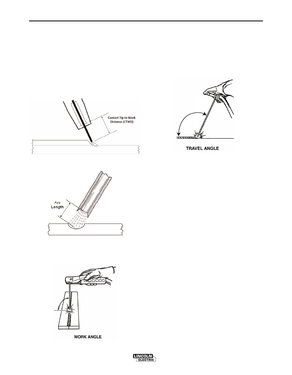
Contact Tip to Work Distance (CTWD) (for VR
GMAW and VR FCAW) and Arc Length (for VR
SMAW(optional))arethedistancesfromthetipofthe
VRGMAW/FCAWgunorVRSMAW(optional)device
to a plane going through the ideal position location.
SeeFiguresB.42andB.43.
Work Angle is the angle between the electrode and
workpieceasseeninFigureB.44.
Travel Angle istheanglebetweentheelectrodeand
the workpiece in the direction of travel. See Figure
B.45.Theupperrightareaofthescreendisplaysifthe
usershouldbepushingordragging.Iftheuserpush-
eswhentheyshouldbedragging,theywillnotreceive
maximum points. For pipe welding, this is the angle
between the electrode and the tangent of the pipe at
thatpoint.
PASS NUMBER
Thepassnumberisdisplayedontheleftcenterofthe
screen. To change the pass being viewed touch the
arrowicons.
TRAVEL DIRECTION
Thetraveldirectionislocatedontherightsideinthe
middle of the screen. When the user first starts to
weld,atraveldirectionissensedbythesystemandan
arrowindicatingthedirectionisdisplayed.Forvisual
cues,thesystemassumesthesedirections.Thevisu-
al cues will automatically adapt to the travel direction
usedwhenthearcisstruck.
BEAD RENDER
Animageofthecompletedpassappearsinthemiddle
ofthescreen.
DISCONTINUITY INDICATOR
Thelowerleftsideofthescreenlistpotentialdisconti-
nuities.SeeFigure B.46.Whenastudentusesincor-
rectweldingtechniques,thiscausesspecificwelddis-
continuities.Alineisdrawnatthelocationindicating
these discontinuities. For example, too long an arc
lengthwillcauseporosity.
VRTEX
®
MOBILE
FIGURE B.42 – CONTACT TIP TO WORk
DISTANCE (CTWD)
FIGURE B.43 – ARC LENGTH
FIGURE B.44 – WORk ANGLE
FIGURE B.45 – TRAVEL ANGLE