Operation (user mode) – Lincoln Electric IM10136 VRTEX MOBILE User Manual
Page 39
B-20
OPERATION (USER MODE)
B-20
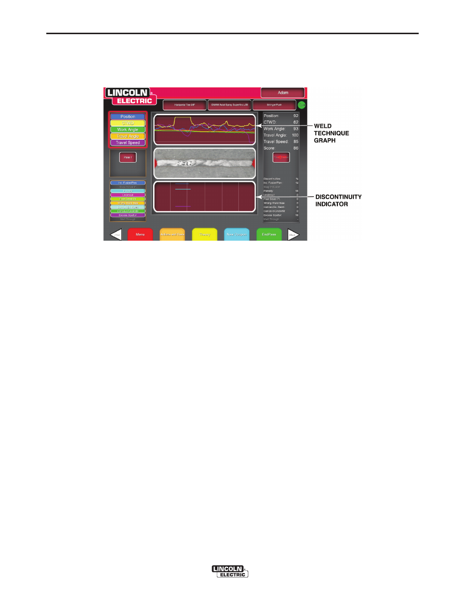
TECHNIQUE PARAMETERS
Theupperleftareaofthescreenshowsthetechniqueparametersbeingtrackedandthegraphoftheseparame-
tersislocatedtotheright.SeeFigureB.41.Whentheuserwelds,eachparameterisgraphedusingalinethat
isofthesamecolorasthetechniqueparameterbox.Forexample,“position”iswrittenintheblueboxandindi-
catedbytheblueline.Theleftsideofthegraphrepresentstheleftsideofthecoupon,andtherightsiderepre-
sentstherightsideofthecoupon.Forverticalwelds,thegraphisrotatedsothatitisvertical,withthebottomrep-
resentingthebottomofthecouponandthetoprepresentingthetopofthecoupon.Thegraphalsoshowshow
closetheparameterwastotheidealvalue.Theidealvalueisindicatedbytheredlinelocatedinthecenterofthe
graph.Thisvalueisdeterminedbythetoleranceeditorsettings.Theupperandlowerwhitelinesrepresentthe
acceptablemaximumandminimumvaluesthattheparametershouldbewithin.Thesevaluesarealsodetermined
bythetoleranceeditorsetting.Anythingabovethetopwhitelineorbelowthebottomwhitelineisoutoftolerance.
Theclosertheuseristotheidealline,thebettertheweld.Eachparametercanbetoggledonoroffofthegraph
bytouchingtheappropriateicon.
VRTEX
®
MOBILE
FIGURE B.41 – LASER SCREEN (GRAPH, DEFECTS, DISCONTINUITIES, ETC.)