Installation, Caution – Lincoln Electric IM10136 VRTEX MOBILE User Manual
Page 13
A-6
INSTALLATION
VRTEX
®
MOBILE
A-6
INSTALLATION
LOCATION
1.Decideonalocationforyourunit.
NOTE: The system requires approximately 8’ L x 8’
D x 8’ H (2.4 m L x 2.4 m D x 2.4 m H) of
space.
Keeptheareafreeofobstructionforatleast3feetin
alldirectionsofboththestandandVRweldmachine.
Inaddition,beconsciousofwhereyouareplacingthe
unittoavoidmagneticfields,conductiveandhighfre-
quencyobjectsandprocesses.
NOTE: Avoid setting up the VRTEX
®
MOBILE near
high frequency TIG machines and power
sources.
Having these types of objects in the area can cause
interferenceandresultinincreasedjitterand/ordistor-
tioninthemotiontracking.
For best results, do not install VRTEX
®
MOBILE
machine in the welding lab. Electrical interference
frompowerlines,thoughgenerallysmall,canbepre-
sent. Therefore all electrical power or lighting wiring
within50feetoftheweldingareashallbeenclosedin
grounded rigid metallic conduit. In the event the
VRTEX
®
MOBILE is affected by interference, it is the
user's responsibility to take steps to isolate and/or
eliminatetheinterference.
An uninterruptible power supply (UPS) may be
required for the protection of the system from power
irregularitiesordisruption.
ItisstronglyrecommendedthatasingleorMulti-Outlet
surge protector be used to protect the machine from
anyunwantedvoltagesaboveasafethreshold.
MULTIPLE SYSTEM INSTALLATIONS
Ifmultiplesystemsarerequiredtooperatetogetherin
one location, a unique frequency transmitter can be
installed during the manufacturing process at Lincoln
Electrictoreducepotentialinterferencebetweensys-
tems. K3165-1 systems have a standard frequency
sourceinstalled.K3165-2systemshaveanalternate
frequencysourceinstalled.Formultiplesysteminstal-
lations, alternate the K3165-1 and K3165-2 systems
forbestoperation:
For Example: If8systemsaretobeinstalledintheVR
welding lab, the standard and alternate frequencies
shouldbepositionedasseenbelow.
MONITOR
1.Placethemonitoronasturdy,flatanddrysurface
approximatelywaisthigh.
2.Placethemachineinalocationthatiscloseenough
tothemonitorsothecablesonthecasebackcan
reachthecouponstandandthemonitor.
Route the cables so they do not create a tripping
hazard.
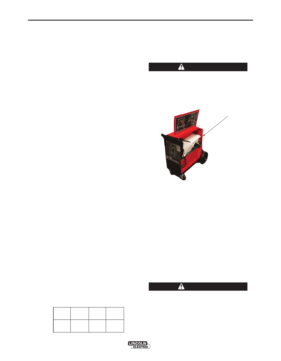
3.Open the component compartment located on the
rightsideofthemachine.SeeFigureA.6.
4.Carefully unwrap and remove the helmet (FMD),
unigun handle, riser arm assembly, coupon riser
stand and base, pins and speakers. See Right
Side Component Compartment Diagram (Figure
A.10).Savepackagingforfutureuse.
5.Hanghelmetonfrontofmachineuntilreadyforuse.
6.Store unigun assembly in the gun bracket located
onthetopofcasefrontuntilreadytouse.
7.Locate and unpackage the following cables from
therearofthemachine;
•RiserArmCable
•AudioVisual(A/V)CableCluster
•MachineInputLineCable
8.Positioncouponriserbasenear,butnotlessthan
18inchesfromthemonitor.Rubbersidedown.
Position coupon riser stand at least eighteen inch-
es from monitor and any potential source of elec-
trical and magnetic interference.
K3165-1
K3165-1
K3165-1
K3165-1
K3165-2
K3165-2
K3165-2
K3165-2
CAUTION
CAUTION
FIGURE A.6 – COMPONENT COMPARTMENT
COMPONENT
COMPARTMENT