Operation, Weld sequence, Start options – Lincoln Electric IM10022 POWER WAVE AC_DC 1000 SD User Manual
Page 39: End options
B-9
OPERATION
B-9
POWER WAVE
®
AC/DC 1000
®
SD
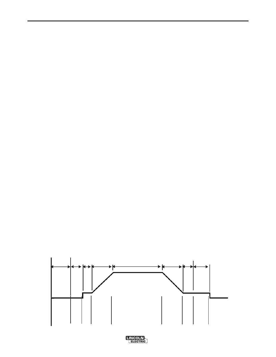
WELD SEQUENCE
The weld sequence defines the weld procedure from
beginning to end. The Power Wave
®
AC/DC 1000
®
SD
not only provides adjustment of basic welding
parameters, but also allows the operator to fine tune
the start and finish of each weld for superior
performance.
All adjustments are made through the user interface.
Because of the different configuration options, your
system may not have all of the following adjustments.
Regardless of availability, all controls are described
below.
START OPTIONS
The Delay, Strike, Start, and Upslope parameters are
used at the beginning of the weld sequence to
establish a stable arc and provide a smooth transition
to the welding parameters.
• ARC DELAY inhibits the wire feed for up to 5 sec-
onds to provide an accurate weld start point.
Typically used in multi-arc systems.
• Strike settings are valid from the beginning of the
sequence (Start Button Pressed) until the arc is
established. They control Run-in (speed at which
the wire approaches the workpiece), and provide
the power to establish the arc.
Typically output levels are increased and WFS is
reduced during the Strike portion of the weld
sequence
• Start values allow the arc to become stabilized once
it is established.
Extended Start times or improperly set parameters
can result poor starting
• Upslope determines the amount of time it takes to
ramp from the Start parameters to the Weld
parameters. The transition is linear and may be up
or down depending on the relationship between the
Start and Weld settings.
END OPTIONS
The Downslope, Crater, Burnback and Restrike
Timer parameters are used to define the end of the
weld sequence.
• Downslope determines the amount of time it takes
to ramp from the Weld parameters to the Crater
parameters. The transition is linear and may be up
or down depending on the relationship between the
Weld and Crater settings.
• Crater parameters are typically used to fill the crater
at the end of the weld, and include both time and
output settings.
• Burnback defines the amount of time the output
remains on after the wire has stopped. This feature
is used to prevent the wire from sticking in the weld
puddle, and condition the end of the wire for the
next weld. A Burnback time of 0.4 sec is sufficient in
most applications. The output level for Burnback is
the same level as the last active weld sequence
state (either Weld or Crater).
• Restrike Timer is used to protect the welding
system and/or work piece being welded. If the arc
goes out for any reason (short circuit or open
circuit), the Power Wave
®
AC/DC 1000
®
SD will
enter a Re-strike state and automatically manipulate
the WFS and output in an attempt to re-establish the
arc. The Re-strike timer determines how long the
system will attempt to re-establish the arc before it
shuts down.
• A Re-strike time of 1 to 2 sec is sufficient in most
applications.
• A Re-Strike setting of “OFF” allows for infinite
restriking attempts until a shutdown occurs.
FIGURE B.9 WELD SEQUENCE
O
ut
pu
t
Strike
Upslope
Weld
Downslope
Time
Arc Start
Delay
Start
Crater Burnback
Sta
rtB
u
tt
o
n
Pressed
Wire
Begi
ns
to
F
ee
d
W
ire
T
o
u
che
s
P
la
te
E
n
do
f
St
a
rt
Time
r
End
o
f
Upslope
S
top
B
u
tt
o
n
P
re
sse
d
En
d
o
f
Down
slope
E
nd
o
fCrate
r
Tim
e
r
En
do
f
Burn
b
ack