Operation, Caution, Multiple arc system considerations – Lincoln Electric IM10022 POWER WAVE AC_DC 1000 SD User Manual
Page 38: Basic modes of operation
B-8
OPERATION
B-8
POWER WAVE
®
AC/DC 1000
®
SD
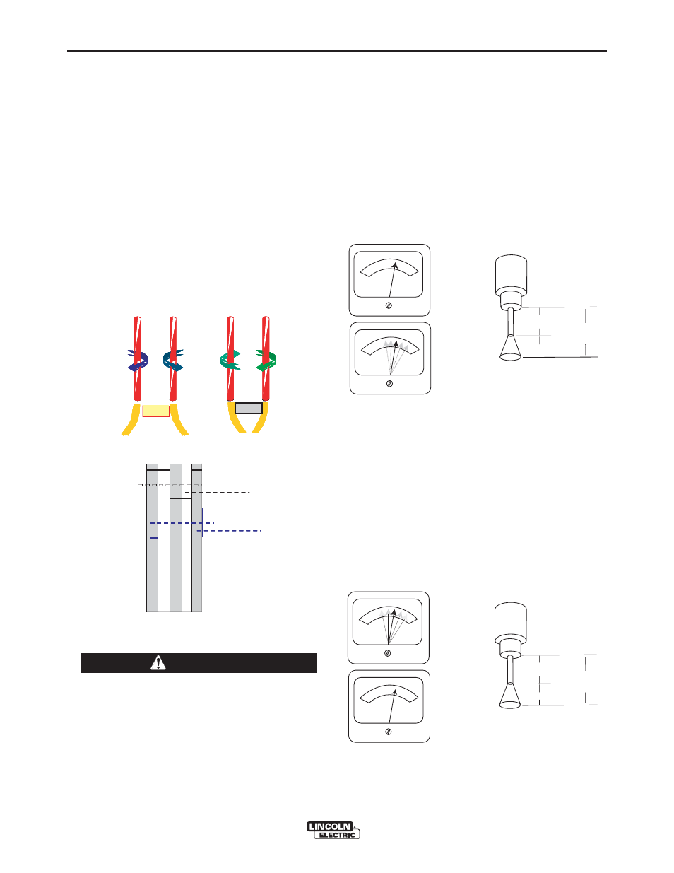
MULTIPLE ARC SYSTEM
CONSIDERATIONS
Large scale SAW applications often employ multiple
arcs to increase deposition rates. In multiple arc
systems, magnetic forces created by like and
opposing weld currents of adjacent arcs can result in
arc interaction that can physically push or pull the arc
columns together. See Figure B.5. To counteract this
effect, the phase relationship between adjacent arcs
can be set to alternate and equalize the duration of
magnetic push and pull forces. This is accomplished
through the synchronizing cables (K1785-xx). Ideally,
the net result is a cancellation of the interacting
forces. See Figure B.6.
Never simultaneously touch electrically "hot"
parts in the electrode circuits of two different
welders. The electrode to electrode no load
voltage of multiple arc systems with opposite
polarities can be double the no load voltage of
each arc. Consult the Safety information located
at the front of the Instruction Manual for additional
information.
------------------------------------------------------------------------
BASIC MODES OF OPERATION
CONSTANT CURRENT (CC)
• Operator presets Current and desired Voltage.
• The Power Source:
- Goal is to maintain a constant arc length.
- Drives a constant Current.
- Synergically Controls WFS to Maintain Voltage
at the desired Set point.
• Arc Length is proportional to Voltage.
• Traditionally used for larger diameter wires and
slower travel speeds.
CONSTANT VOLTAGE (CV)
• Operator presets Wire Feed Speed and desired
Voltage
• The Power Source:
- Goal is to maintain a constant arc length.
- Commands constant wire feed speed
- Synergically Controls Current to Maintain
Voltage at the desired Set point
• Arc Length is proportional to Voltage
• Traditionally used for smaller diameter wires and
faster travel speeds.
FIG. B.5 - ARC INTERFERENCE
+
-
-
+
PUSH
+
+
-
-
PULL
+
-
-
+
+
-
+
PUSH
+
+
-
-
PULL
PUSH
+
+
-
-
+
+
-+
+
-
-
PULL
FIG. B.6 SYNCHRONIZED ARCS
Lead Arc
Trai l Arc
P
o
s
it
ive
Negati
v
e
Pos
it
ive
P
ositive
Negative
N
egative
P
os
itive
Negative
Positive
Negative
Lead Arc
Trai l Arc
P
US
H
P
U
S
H
PUS
H
PULL
PULL
CAUTION
Extension
Heating= Vir
Arc Length= Varc
Total Electrical
Stick out
V= Vir+Varc
TO
MAINTAIN CONSTANT
ARC LENGTH
AND
WIRE FEED
SPEED VARIED
CURRENT HELD
CONSTANT
AMPS
WIRE FEED SPEED
Extension
Heating= Vir
Arc Length= Varc
Total Electrical
Stick out
V= Vir+Varc
TO
MAINTAIN CONSTANT
ARC LENGTH
AND
WIRE FEED SPEED
HELD CONSTANT
CURRENT VARIED
AMPS
WIRE FEED SPEED
FIGURE B.7 - CONSTANT CURRENT
FIGURE B.8