4 jumper settings, Umper, Ettings – IEI Integration IMBA-9454 v4.02 User Manual
Page 101: Figure 5-8: jumper locations, Table 5-1: jumpers
IMBA-9454G Motherboard
Page 83
Step 3:
Insert the DIMM. Once properly aligned, the DIMM can be inserted into the
socket. As the DIMM is inserted, the white handles on the side of the socket will
close automatically and secure the DIMM to the socket. See Figure 5-7.
Step 4:
Removing a DIMM. To remove a DIMM, push both handles outward. The
memory module is ejected by a mechanism in the socket.
Step 0:
5.4 Jumper Settings
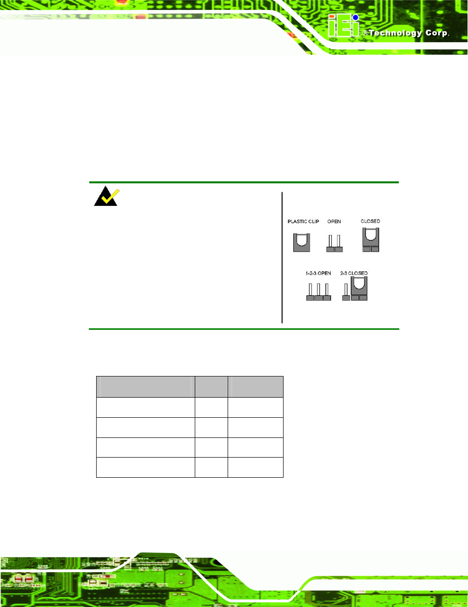
NOTE:
A jumper is a metal bridge used to close an
electrical circuit. It consists of two or three metal
pins and a small metal clip (often protected by a
plastic cover) that slides over the pins to connect
them. To CLOSE/SHORT a jumper means
connecting the pins of the jumper with the plastic
clip and to OPEN a jumper means removing the
plastic clip from a jumper.
Figure 5-8: Jumper Locations
Before the IMBA-9454G is installed in the system, the jumpers must be set in accordance
with the desired configuration. The jumpers on the IMBA-9454G are listed in Table 5-1.
Description
Label
Type
CF Master/Slave Selection
JP2
2-pin header
Clear CMOS
JP1
3-pin header
COM2 Mode Selection
JP4
3-pin header
SPI Flash Connector
JSPI1
8-pin header
Table 5-1: Jumpers