Table 3-22: lan2_usb2 connector pinouts, Table 3-23: lan1_usb1 connector pinouts, Table 3-23 – IEI Integration KINO-AQ870 User Manual
Page 51
KINO-AQ870
P a g e 39
P5
LAN2_MDIN1
P6
LAN2_MDIP2
P7
LAN2_MDN2
P8
LAN2_MDIP3
P9
LAN2_MDIN3
P10
GND
P11
LAN2_LINK100
P12
LAN2_LINK1000
P13
LAN2_ACT-1
P14
+V3.3A_LAN2
U1
+USB_PWR1
U2
USB20_C_N10
U3
USB20_C_P10
U4
GND
U5
+USB_PWR1
U6
USB20_C_N11
U7
USB20_C_P11
U8
GND
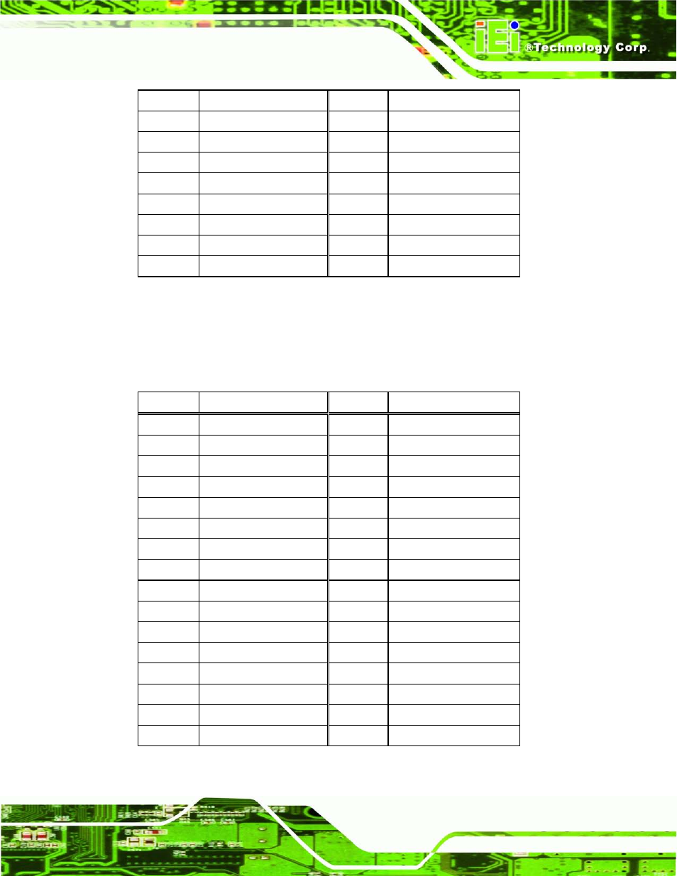
Table 3-21: LAN2_USB2 Connector Pinouts
The USB 3.0 ports are for attaching USB 3.0 peripheral devices to the system. To be able
to use the USB 3.0 ports, please make sure the USB 3.0 function is enabled in BIOS (see
Section 5.3.7). The pinouts of LAN2 and USB 3.0 connectors are shown below.
PIN NO.
DESCRIPTION
PIN NO.
DESCRIPTION
1
USB3_PWR1
2
USB2P0_DM1
3
USB2P0_DP1
4
GND
5
USB3P0_RXDN1
6
USB3P0_RXDP1
7
GND
8
USB3P0_TXDN1
9
USB3P0_TXDP1
10
USB3_PWR2
11
USB2P0_DM2
12
USB2P0_DP2
13
GND
14
USB3P0_RXDN2
15
USB3P0_RXDP2
16
GND
17
USB3P0_TXDN2
18
USB3P0_TXDP2
19
+0.9V_LAN1
20
LAN1_MDIP0
21
LAN1_MDIN0
22
LAN1_MDIP1
23
LAN1_MDIN1
24
LAN1_MDIP2
25
LAN1_MDIN2
26
LAN1_MDIP3
27
LAN1_MDIN3
28
GND
29
+3.3V_LAN1
30
LAN1_LINK_ACT#
31
LAN1_100#
32
LAN1_1000#
Table 3-22: LAN1_USB1 Connector Pinouts