Warner Electric MCS2000-PSDRV2 User Manual
Page 9
9
Warner Electric • 800-825-9050
P-2010-7 • 819-0525
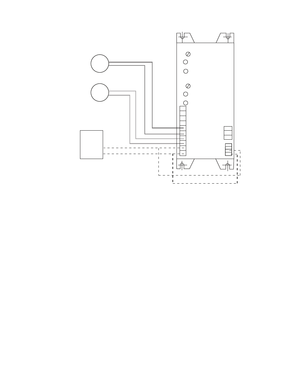
Brake
Brake
“A”
“B”
24 Volt
Power
Supply
- DC
+DC
MSC2000-DRV2
“A” Antiresidual
Channel A
“B” Antiresidual
Channel B
1. In A 0-10V
2. 0V
3. In B 0-10V
4. 0V
5. Brk A+
6. Brk A-
7. Brk B+
8. Brk B-
9. -DC Power
10. + 24 - 48 VDC
Figure 4 24 Volt System Power Supply and Brake Wiring
Wiring with 24 volt DC External Power Supply
Wiring using internal 24 volt DC Power
MCS2000-PSDRV2 Power Supply /Driver
Note: If the internal power supply is used, the
maximum current available is 3.1 amps. If higher
current is required, then either a second
MCS2000-PS power supply is required or an
external 24 VDC source is needed in place of the
internal supply.
48 Volt Systems
o 1.
Wire the positive (+) side of the 48 volt DC
power supply to terminal 10 of the
MCS2000-PSDRV2. Make sure that the
terminal is securely tightened on the
MCS2000-PSDRV2.
o 2.
Wire the negative side (-) or DC common
of the 48 volt DC power supply to terminal
9 of the MCS2000-PSDRV2. Make sure the
terminal is securely tightened on the
MCS2000-PSDRV2.
Note: Make sure the current capacity is
sufficient to handle the brake load and
driver circuitry. If any other external power
requirements are required, then the power
supply capacity must be sized to handle
these currents as well.
o 3.
Wire the brake for Channel “A” on
terminals 5 and 6 of the MCS2000-
PSDRV2. Make sure the terminals are
securely tightened.
o 4.
If a brake is to be used on Channel “B”
wire the brake to Channel “B” terminals 7
and 8 on the MCS2000-PSDRV2. Make
sure the terminals are securely tightened.